Section 7
Soil Vapor and Indoor Air Sampling Guidance
Interim Final – December 2017
Section 7.0 Introduction
Section 7.1 Occurrence of Subsurface Vapor Plumes
Section 7.2 Soil Vapor Transport Mechanisms and Conceptual Site Models
7.2.1 Factors Affecting Subsurface Vapor Flow and Impacts to Indoor Air
7.2.2 Preparation of Conceptual Site Models for Soil Vapor Investigations
Section 7.3 Development of Vapor Intrusion Screening Tools
Section 7.4 Soil Vapor Investigations
Section 7.5 Collection of Representative Soil Vapor Samples
Section 7.6 Soil Vapor Sampling Strategies
7.6.1 Determining When to Collect Soil Vapor Samples
7.6.2 Soil Vapor Sampling Design
7.6.2.1 Overview
7.6.2.2 Soil Vapor Sampling Point Locations
7.6.2.3 Soil Vapor Sample Depths and Depth Intervals
7.6.2.4 Soil Vapor Sample Screen Intervals
Section 7.7 Indoor Air Sampling Strategies
7.7.1 Determining When to Collect Indoor Air Samples
7.7.2 Indoor Air Sampling Design
Section 7.8 Sampling Approaches and Equipment
7.8.1 Whole Air Sampling
7.8.1.1 Summa Canisters
7.8.1.2 Tedlar Bags
7.8.1.3 Whole Air Sample Handling
7.8.2 Sorbent Tube Sampling
7.8.3 Passive Sampling
7.8.3.1 Passive Soil Vapor Sample Collectors
7.8.3.2 Passive Sampling of Indoor Air
7.8.3.3 Emerging Technologies
7.8.4 Large Volume Purge Sampling
7.8.4.1 Investigation Objectives and LVP DU Designation
7.8.4.2 LVP Sample Point Designation and Slab Preparation
7.8.4.3 LVP Sample Train Design and Test
7.8.4.4 Extraction Point Installation
7.8.4.5 LVP Sample Collection
7.8.4.6 Data Quality Control
7.8.4.7 LVP Investigation Report
7.8.5 Flux Chamber Sampling
Section 7.9 Active Soil Vapor Probe Installation
7.9.1 Temporary Probes
7.9.2 Permanent Probes
7.9.3 Additional Recommendations for Subslab Probes
7.9.4 Soil Vapor Probe Tubing
7.9.5 Soil Vapor Probe Abandonment
Section 7.10 Active Soil Vapor Sampling Procedures
7.10.1 Soil Vapor Sample Timing and Frequency
7.10.2 Soil Vapor Probe Equilibration
7.10.3 Soil Vapor Probe Purging
7.10.3.1 Flow Rate
7.10.3.2 Vacuum Conditions and Tight Soils
7.10.4 Soil Vapor Sampling Trains
7.10.5 Soil Vapor Probe Leak Testing
7.10.5.1 Sampling Train Shut-In Test
7.10.5.2 Water Dam Vapor Point Test
7.10.5.3 Tracer Method 1 – Application of Tracer Gas to Surface Completion Point Only
7.10.5.4 Tracer Method 2 – Application of Tracer Gas to Entire Sampling Apparatus
7.10.5.5 Tracer Gas Concentration Measurement
7.10.5.6 Selection of Leak Check Compound
7.10.6 Soil vapor sample collection steps
7.10.7 Soil Vapor Sample Notes and Logs
Section 7.11 Active Indoor Air Sample Collection Procedures
7.11.1 Initial Building Survey
7.11.2 Indoor Air Sample Locations
7.11.3 Indoor Air Sample Duration
7.11.4 Indoor Air Sample Frequency
7.11.5 Indoor Air Sample Containers And Analytical Methods
7.11.6 Indoor-Outdoor Air Sample Logs
Section 7.12 Passive Soil Vapor and Indoor Air Sample Collection Procedures
7.12.1 Passive Sampling of Soil Vapor
7.12.2 Passive Sampling of Indoor Air
Section 7.13 Soil Vapor And Indoor Air Sample Analysis
7.13.1 Available Analytical Methods
7.13.1.1 Volatile Organic Compounds (VOCs)
7.13.1.2 Total Volatile Petroleum Hydrocarbons
7.13.2 Choosing the Analytical Method
7.13.3 Field Analytical Methods
7.13.4 Quality Control Samples
7.13.4.1 Field Quality Control
7.13.4.2 Laboratory Quality Control
Section 7.14 Data Evaluation
7.14.1 Soil Vapor Sample Evaluation
7.14.2 Indoor Air Sample Evaluation
7.14.3 Additional Evaluation and Remedial Actions
Section 7.15 Documentation of Soil Vapor or Indoor Air Sampling
Figures
7-1 Example Vapor Plume Contours and Vapor Intrusion Pathways.
7-2 Conceptual Model of Soil Vapor Transport Including Biodegradation Process.
7-3 Complete Exposure Pathway CSM for Soil Vapor to Indoor Air.
7-4 Schematic of Soil Vapor Concentration Profile.
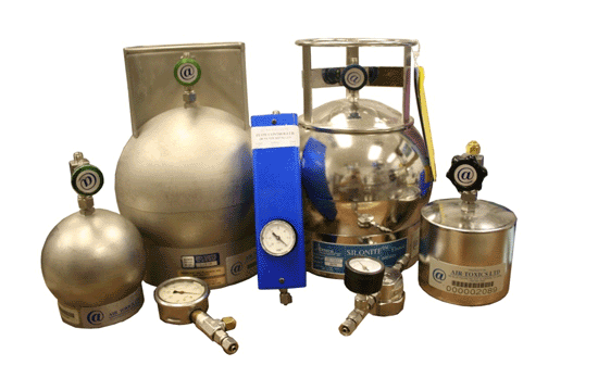
7-5 Summa Canisters (spherical and cylindrical containers) with Flow Controllers (smaller gauges and blue box).
7-6 Summa Canister and Flow Controller Setups (note smaller flow controller on left).
7-7 Summa Canister and Flow Controller Parts.
7-8 One-liter Tedlar Bag with Disposable Syringe and Three-way Valve for Filling.
7-9 Sorbent Tubes.
7-10 Two Examples of Passive Soil Vapor Sample Collectors.
7-11 Two Examples of Indoor Air Passive Sample Collectors.
7-12 Passive Diffusion Sampler (PDS)
7-13 Summary of high-density, passive sampler data for PCE vapors beneath the slab of a former dry cleaner.
7-14 Designation of soil vapor DU beneath a building slab for collection of LVP samples.
7-15 Example options for designation of purge points for collection of LVP subslab vapor samples.;
7-16 Floor drain and suspect deep cracks sealed with bentonite slurry.
7-17 Simplified schematic of Large Volume Purge sampling train.
7-18 Example design of LVP sample collection system.
7-19 Installation of LVP vapor extraction point used in HDOH (2017) field study.
7-20 Example, completed field LVP sample collection set up.
7-21 Schematic Diagram and Photograph of Flux Chamber
7-22 Typical Temporary Soil Vapor Probe
7-23 Installing a Temporary Soil Vapor Probe Using a Direct-Push Drill Rig
7-24 Vapor Point Completions
7-25 Typical Nested Permanent Soil Vapor Sampling Probes
7-26 Installation of a Permanent Soil Vapor Probe
7-27 Schematic of Typical Sub-Slab Soil Vapor Sampling Probe (see also Figure 7-28 & 7-29).
7-28 Sub-Slab Soil Vapor Sampling Probes
7-29 Sub-Slab Soil Vapor Sampling Probes
7-30 Installation of a Vapor Pin™ with a silicone sleeve directly into slab
7-31 Soil Vapor Probe Purging Devices
7-32 Example Vacuum Gauges for Purging and Sample Collection using a Summa Canister Sampling Train (see also Figure 7-34 and Figure 7-35).
7-33 Lung Boxes with Tedlar bag. Vacuum is drawn on sealed lung box, causing the Tedlar bag to pull vapor from the collection point and fill.
7-34 Summa canister sampling trains.
7-35 Example Soil Vapor Sample Collection Setups
7-36 Soil Vapor Sampling Trains Arranged for Shut-in Test (see also Figure 7-35)
7-37 Example PVC Coupling “Water Dam” Sealed to Floor with Inert Putty for Leak Testing Slab-mounted Vapor Point
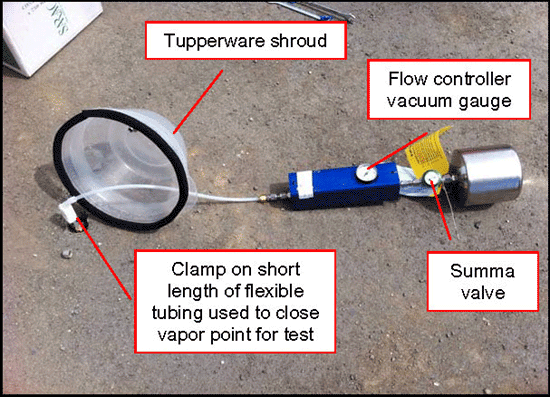
7-38 Shroud Over Vapor Probe Surface Completion
7-39 Method 2 Helium Shroud Leak Testing Systems
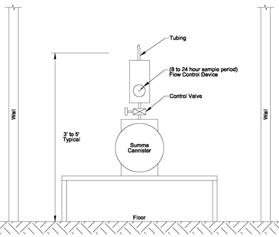
7-40 Typical Summa Canister Indoor Air Sampling Apparatus.
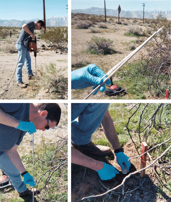
7-41 Installing a Passive Soil Vapor Sample Collector by Hand.
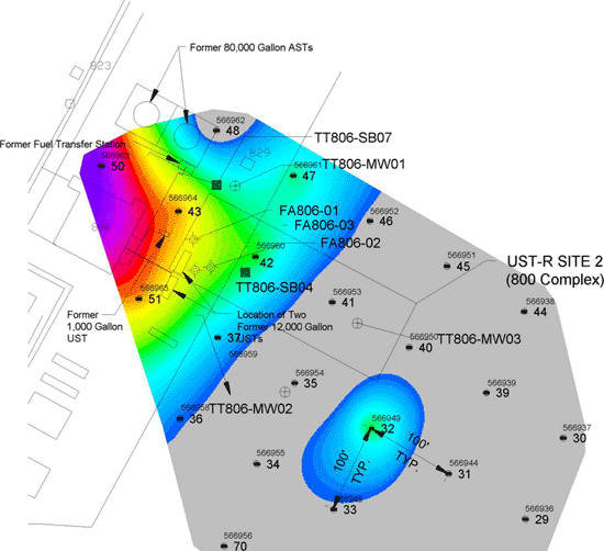
7-42 Example Plume Map from Grid-based Passive Soil Vapor Survey.
7-43 Typical Duplicate Sampling Apparatus (see also Figure 23)
Tables
7-1 Decision Logic for Subsurface Vapor Hazards
7-2 Comparison of HEER Indoor Air Action Levels to Typical Indoor Air Concentrations of Common VOCs.
7-3 Comparison of Soil Vapor & Indoor Air Sampling Approaches
7-4 Common Soil Vapor Concentration Unit Conversion Factors
7-5 Comparison of TCE and PCE Results for Passive Diffusion Sampler and Active Soil Gas Sample
7-6 Sand Pack Porosity Volume (ml)
7-7 Tubing Volume (ml)
7-8 Comparison of Tracer Leak Check Methods
7-9 Comparison of Leak Check Tracers
7-10 Summary of Soil Vapor & Indoor Air Analytical Methods1
7-11 HDOH-Recommended Laboratory Analytical Methods for Soil Vapor or Indoor Air Contaminants and Leak Detection Compounds
Return to the Top of the Page
7.0 SOIL VAPOR AND INDOOR AIR SAMPLING GUIDANCE
This section of the Technical Guidance Manuall addresses the collection of subsurface soil vapor samples and indoor air samples. The guidance was developed following review of numerous guidance manuals, sampling protocols, technical reports and advisories published by the United States Environmental Protection Agency (USEPA) and other states, as well as other publications. A list of references consulted during development of this guidance is included at the end of the section.
The discussion of sample collection is preceded by an overview of the occurrence and nature of vapor plumes in the subsurface and the potential risks posed to outdoor air and overlying buildings. The development of HDOH soil, groundwater and soil gas (“vapors”) action levels for evaluation of vapor intrusion hazards is described in the document Evaluation of Environmental Hazards at Sites with Contaminated Soil and Groundwater (“EHE guidance;” HDOH, 2016, see also HDOH, 2016b.). The discussion provided below and in Section 13 is intended to serve as a supplement to this guidance.
7.1 OCCURRENCE OF SUBSURFACE VAPOR PLUMES
Sites where releases of volatile organic compounds (VOCs) can be of concern include commercial, military and industrial fuel facilities with petroleum storage tanks and pipelines; degreasing, cleaning or dry cleaning operations where chlorinated solvents are utilized; and agricultural operations where fumigants such as dibromochloropropane were stored, mixed or applied. The size of contaminated sites can range from a few hundred square feet associated with a small, one-time release from an underground storage tank to several acres associated with large long-time releases from fuel pipelines and aboveground storage tanks.
The emission of volatile chemicals from contaminated soil and groundwater can create a plume of vapors in the vadose zone. These plumes can adversely impact indoor air if drawn into an overlying building, a key topic of this section. Vapors emitted at the ground surface can also affect outdoor air. This issue is addressed separately under direct-exposure models for contaminated soil, however, and is considered to pose less of a threat to human health than vapor intrusion into buildings (see HDOH, 2016). Vapors in vadose-zone soil could also migrate downwards and impact groundwater that has otherwise not been directly affected by the release. This has been recognized, for example, at MTBE release sites on the mainland.
The majority of subsurface vapor plumes in Hawai´i are associated with subsurface released petroleum fuels including gasoline, diesel and jet fuel. As discussed in Section 7.13, vapors emitted from petroleum fuels are evaluated in terms of Total Petroleum Hydrocarbons (TPH) and a short list of individually targeted, individual compounds including benzene, toluene, ethylbenzene, xylenes (BTEX), methyl tertiary butyl ether (MTBE, not widely used in Hawaiʻi) and naphthalene (see also Section 9). Methane, a biological breakdown product of petroleum or a component of landfill gas, can also be of importance at some sites. As discussed in Section 7.6, petroleum-related vapor plumes that could pose hazards for overlying buildings are almost always associated with the presence of relatively shallow, free product in vadose-zone soil or groundwater (see USEPA 2013). Under most site scenarios, the breakdown of petroleum compounds by naturally occurring bacteria in the soil will ensure that vapor plumes rarely migrate more than 15 to 30 feet vertically through unconsolidated soil and more than one-hundred feet laterally under pavement or buildings from the source area (see Section 7.6.1).
A smaller number of subsurface vapor plumes in Hawaiʻi are associated with releases of chlorinated solvents from dry cleaners (e.g., tetrachloroethene or “PCE”) or parts washing operations (e.g., trichloroethene or “TCE”). Vapors emitted from these releases are evaluated in terms of the primary product released as well as related breakdown chemicals, such as dichloroethenes or dichloroethanes and vinyl chloride. Although the volume of product released is typically much smaller in comparison to releases of petroleum fuel, the higher toxicity and in particular the greater persistence of chlorinated solvents can lead to potential vapor intrusion concerns even in the absence of free product in soil or groundwater. Dilute plumes of solvent-contaminated groundwater have, for example, been documented to travel thousands of feet downgradient of initial release areas and impact overlying homes and buildings (e.g., see API 2005, USEPA 2004e, USEPA 2012)
Both chlorinated solvents and non-chlorinated petroleum products could be present at some sites. Common examples include dry cleaning facilities that have a fuel tank associated with a boiler and/or that used Stoddard solvent during an earlier period of operation. The presence of high levels of vinyl chloride in groundwater or soil vapor at sites often indicates the presence of co-located petroleum contamination. The vinyl chloride is associated with reductive dechlorination of chlorinated solvents in the presence of petroleum. The presence of significant breakdown products in soil vapor or groundwater signifies the need to look for petroleum contamination in the same area.
Due to the inherent heterogeneity of VOCs in subsurface vapor plumes and the uncertainty of upward vapor migration from deeper areas, HDOH emphasizes the collection of soil vapor samples from immediately beneath a building slab for evaluation of potential vapor intrusion hazards (see Section 7.6.2.3). The concurrent collection and evaluation of deeper soil vapor samples is also typically recommended for heavily-contaminated properties. Data from deeper samples may indicate a need to seal cracks and gaps in floors as an added measure of protection even in cases where subslab data do not suggest a significant problem (see Subsection 7.14.1).
7.2 SOIL VAPOR TRANSPORT MECHANISMS AND CONCEPTUAL SITE MODELS
7.2.1 FACTORS AFFECTING SUBSURFACE VAPOR FLOW AND IMPACTS TO INDOOR AIR
As introduced in the previous section, understanding how vapors are generated, migrate in the subsurface and can intrude an overlying building is important for development of site investigation objectives and associated sampling plans. In theory, the rate and flux of VOC diffusion through the vadose zone is relatively simple to model (e.g., see USEPA 2004e). In practice, estimation of the upward, mass flux of vapor-phase VOCs in the subsurface and prediction of VOC concentrations in subslab soil vapor is very difficult.
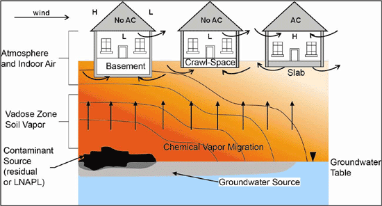
Figure 7-1: Example Vapor Plume Contours and Vapor Intrusion Pathways. Vapor-phase chemicals diffuse away from a source area. Wind effects (or heating) can cause depressurization of buildings and advective intrusion of vapors. Air conditioning (AC) can over pressurize a building as fresh air is brought inside and induce an outward flow of air into the subslab space. Source: Modified from API 2005. Upward migration of vapors dominated by diffusion; advective flow limited to near vicinity (a few feet or less) of floors of under-pressured buildings.
Concentrations of VOCs in shallow or subslab soil vapor are oftentimes significantly lower than would be predicted by models based on the soil type observed in the field (see HDOH, 2016, USEPA, 2012). This is due in part to dissolution of vapors into soil moisture but can also include adsorption to or diffusion into clays in the soil and permanent removal from the vapor plume, a mechanism not directly taken into account in the vapor intrusion models. The heterogeneous nature of contaminant distribution in soil, both sorbed to soil particles and in vapor phase, complicates the collection of representative data. These factors highlight the need to collect soil vapor data in the immediate vicinity of potentially affected buildings as a routine part of vapor intrusion studies when general site knowledge suggest a potentially significant vapor intrusion risk. Limitations on the utility of traditional, small-volume sample data due random, small-scale heterogeneity can also be overcome by the collection of “Large Volume Purge” vapor samples beneath building slabs (Section 7.8.5).
Vapors migrate in subsurface soils primarily by diffusion from high- to low-concentration areas (Figure 7-1). Vapors diffuse much more rapidly through air-filled pore space than water-filled pore space. Advective flow of vapors caused by pressure differentials (e.g., flow from high- to low-pressure areas) can occur in the near proximity (few inches to few feet) of building floors in cases where the building is under-pressured in comparison to subsurface soils. This can be due to wind effects, changes in barometric pressure due to storms, heating of buildings (unlikely in Hawaiʻi), or the use of exhaust fans in kitchens or shop areas (see Figure 7-1; see also USEPA 2004e, ITRC 2007, USEPA 2012d). Wind-induced depressurization of buildings will be the most likely cause of vapor intrusion in Hawaiʻi. Wind can create a low-pressure zone on the downwind side of a building. Air pulled out of the building as a result can lead to the advective flow of subsurface vapors through cracks and gaps in the floor. This is taken into account in building and HVAC system design.
Buildings with HVAC systems (“Heating, Ventilation and Air Conditioning”) are specifically designed to minimize the infiltration of outdoor air via pathways other than the fresh air intake, in order to ensure efficiency and control costs. More likely for buildings in Hawaiʻi, air conditioning will cause buildings to be over-pressured as fresh air is pulled into the HVAC system ((Roberson et al 1998; see Figure 7-1). This could induce the outward flow of indoor air into subslab soils (see also USEPA 2012d). Samples of subslab soil vapor would in turn reflect the concentration of VOCs in indoor air samples, rather than a subsurface source. This presumably explains the apparent absence of significant vapors immediately beneath slabs of air-conditioned buildings that overlie shallow, petroleum free product or heavily contaminated soil. In this case, the sudden, upward “attenuation” of deeper soil vapors in the immediate vicinity of a building slab is not attributable to biodegradation.
Note that an upward diffusion of vapors into the subslab area could also occur when the air conditioning is turned off in the night time and on weekends. This issue has not been studied in detail. In theory, this could lead to the intrusion of subsurface vapors into the building during these time periods. In practice, this is likely to be offset by the time required for deeper vapors contaminants to diffuse into the zone of advective transport. Impacts to indoor air by intruding vapors are also likely to be offset by increased impacts from indoor sources (see Subsection 7.7). Impacts to indoor air from both subsurface and indoor sources during periods when the building air conditioning system is not operating are generally transient in nature, with contaminants quickly removed upon restart of the HVAC system. Additional information on this topic will be found in Brewer et al. 2014, in prep.
Evaluation of risk posed to occupants should be based on air quality during normal building operating conditions (see also Section 7.10.1). More detailed sampling could be required on a site-specific basis, however, at sites considered to be of high risk for potential vapor intrusion.
Concentrations of volatile chemicals in indoor air associated with indoor sources are also likely to increase when the building HVAC system has been turned off and reach levels significantly higher than reported for typical, indoor air (see Subsection 7.7.2). These types of temporal changes associated with operation of the building HVAC system are important to recognize as part of a vapor intrusion investigation and to consider when determining the timing and frequency of sample collection (see Section 7.10.1). As discussed in Section 7.11, if indoor air samples are desired or required to further assess potential vapor intrusion hazards then they should be collected under normal building ventilation and operation conditions that reflect periods when the building is occupied. This more accurately reflects the potential risk to occupants of the building.
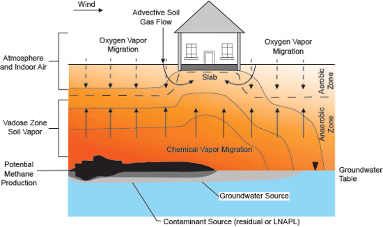
Figure 7-2: Conceptual Model of Soil Vapor Transport Including Biodegradation Process. Source: Adapted from API 2005. Note hypothetical anaerobic zone immediately beneath the building due to biodegradation of vapor-phase petroleum compounds and inadequate replenishment of oxygen.
In Hawaiʻi, seasonal weather variations typically include the “wet” season during the winter, and the “dry” season during the summer. The water table rises and falls accordingly. The magnitude of this rise and fall is minimal in coastal areas near sea level. In inland areas the seasonal water table fluctuation can reach ten feet or more, however. The rise and fall of the water table can create a smear zone of contaminated soil of equal magnitude, especially in the case of petroleum releases that have reached groundwater. As the water table falls and exposes this smear zone, an increase in vapor emissions can occur. As the water table rises some product may rise with it and continue to pose vapor emission hazards. A substantial portion is likely to remain trapped in the smear zone below the water table, however. This can result in a substantial reduction in vapor emissions during the wet season. The collection of deep and/or subslab soil vapor samples during both the wet and dry season is, recommended for sites where exposure of a significant smear zone could vary dramatically over the year (see Section 7.10.1).
The rise and fall of the water table with fluctuating tides could also influence the migration of vapors in the vadose zone. Indoor air could be pulled out of the building and into the subslab zone as the water table falls. The same air, or a mixture of this air and VOCs from subsurface contamination, could be pushed back into the building as the water table rises if the building was not over-pressured. This phenomenon has not been studied in detail in Hawaiʻi. Small, tide-related fluctuations of the water table observed in coastal areas of Hawaiʻi, typically less than one-foot, are unlikely to cause significant fluctuations in vapor concentrations due to exposure and flooding of smear zones. Tidal pumping of air into and out of a building could also help maintain a well-oxygenated zone under a building slab and help protect against significant vapor intrusion associated with subsurface, petroleum contamination.
As discussed in Section 7.10.1, consideration of tidal pumping is not necessary for general screening purposes. The collection of subslab soil vapor samples during periods of both falling and rising water table may be recommended or required, however, at sites that overlie significant, shallow contamination.
7.2.2 PREPARATION OF CONCEPTUAL SITE MODELS FOR SOIL VAPOR INVESTIGATIONS
Consideration of subsurface vapors and the potential for soil vapor intrusion should be included in an overall conceptual site model (CSM) and used to design sampling strategies. The CSM should include information on the expected subsurface geology, depth to the potential source contaminants or groundwater, and actual or potential human or environmental receptors, as well as other specific information described in Section 3. The CSM should be used to develop a general understanding of the site, evaluate potential risks to public health and the environment, and assist in identifying and setting priorities for planned activities at the site.
The CSM should reflect the representative, average subsurface conditions and building susceptibility to vapor intrusion over time and during normal building operation. This is important, because the soil gas (and indoor air) action levels are based on average exposure over a six-year time period (noncancer hazard; e.g., TPH) to thirty-year time period (cancer risk; e.g., benzene and PCE). A focus on soil vapor samples collected during periods of high water table or vapor flux assumptions during periods when a building is over-pressurized can lead to the underestimation of potential vapor intrusion hazards. A focus on subsurface data collected during periods of low water table or periods when the building is under-pressured and most susceptible to vapor intrusion could overestimate the actual risk and lead to unnecessary remedial actions. An understanding of subsurface and building conditions throughout the year as part of the CSM is therefore very important.
A simple conceptual model of soil vapor transport includes the outward diffusion of vapor-phase chemicals from impacted soil or groundwater and the potential advective flow of the vapors into an overlying building (Figure 7 1). The chemicals could migrate to and intrude residential or commercial/industrial building interiors. Common vapor intrusion pathways into buildings include basements, crawl spaces, cracks, and utility penetrations in concrete slabs. The intruding vapors subsequently mix with indoor air and the concentration of initial chemicals in the vapors is attenuated.
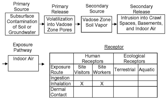
Figure 7-3: Complete Exposure Pathway CSM for Soil Vapor to Indoor Air.
A more detailed conceptual model of soil vapor transport might consider spatial temporal variations in subsurface conditions and building operations (e.g., daily or seasonally). Concentrations of VOCs beneath the slab of a home or building are likely to be heterogeneous (USEPA 2012d; Brewer et al. 2014, in prep). This factor and uncertainty regarding specific, vapor entry routes complicates the investigation of potential vapor intrusion hazards. As discussed in Section 7.6.2.2, the biased collection of subslab soil vapor samples from center of slabs, presumed to be the worst-case area for vapor accumulation as well as potential vapor entry points in other areas of the building (e.g., cracks in floor and utility gaps) is recommended.
The CSM could also include biodegradation processes commonly observed with petroleum hydrocarbon or volatile organic compounds (VOC) impacted soil and groundwater (Figure 7-2). The biodegradation processes include aerobic and anaerobic degradation of contaminants and potential production of additional chemicals of concern (referred to as daughter products). These conditions could change over time, as the release ages. The vapor transport of daughter products, oxygen, CO₂, and in the case of petroleum hydrocarbons, methane, should be considered when assessing aerobic or anaerobic biodegradation processes.
The exposure pathway for soil vapor should be included on the CSM, which serves as the basis of an exposure assessment (see HDOH, 2016). An exposure pathway is defined as “the course a chemical or physical agent takes from the source to the exposed individual”. A completed exposure pathway to a potential receptor has the following four elements: (1) a source of contamination, (2) a contaminant release mechanism, (3) an environmental transport mechanism, and (4) an exposure route at the receptor contact point with the chemicals of concern. An example of a complete exposure pathway CSM diagram for soil vapor to indoor air is provided in Figure 7-3.
For the chemicals of concern to reach a potential receptor, each of the four elements of an exposure pathway must exist and must be complete. If any of these four elements are missing, the path is considered incomplete and does not present a means of exposure under the conditions assumed in the CSM. Common pathways for vapor intrusion from the subsurface are cracks or utility penetrations through the slab or basement walls/floor, sumps with earthen floors, and drain pipes (see Section 7.7.2). Bathrooms, kitchens and utility rooms are often the primary entry points for intruding vapors.
As discussed in Sections 7.6.2 and 7.10.1, it is important that a well-thought-out CSM be prepared prior to an investigation and used to help determine the number and location of vapor collection points as well as the frequency and timing of sample collection. See Section 3 for more information on designing a CSM. See Subsection 13 and the HEER Office EHE guidance for details on environmental hazard evaluation. Section 7.14 discusses the use of a multiple-lines-of-evidence approach to evaluate potential vapor intrusion hazards on a site-specific basis for cases where a high risk of vapor intrusion is identified.
7.3 DEVELOPMENT OF VAPOR INTRUSION SCREENING TOOLS
Assumptions regarding the local nature of vapor intrusion and building ventilation can be used to develop environmental action levels for rapid screening of suspect sites. Development of the HDOH soil, groundwater and soil gas (“vapor”) action levels for vapor intrusion is discussed in the HDOH EHE guidance document (HDOH 2016; see also HDOH, 2016b.). A detailed discussion of indoor air:subslab soil gas attenuation factors selected for use in Hawaiʻi is provide in Section 13 and serves as a supplement to the EHE guidance.
Application of the guidance and screening tools at petroleum-contaminated sites was evaluated in the HDOH study entitled Field Investigation of the Chemistry and Toxicity of TPH in Petroleum Vapors: Implications for Potential Vapor Intrusion Hazards (HDOH, 2012). The results of this study were incorporated into the petroleum section of the HDOH EHE guidance (HDOH 2016). A Question and Answer fact sheet on this document provides additional clarification on the application of the guidance and screening tools at petroleum-contaminated sites (HDOH, 2012c).
As discussed in Section 13 and the EHE guidance, the selected attenuation factors and associated HDOH action levels for vapor intrusion may not be adequately conservative for use in colder regions on the US mainland and elsewhere. Adjustment of the action levels to assumptions regarding vapor flux and building ventilation is required and should be discussed with the overseeing regulatory agency.
7.4 SOIL VAPOR INVESTIGATIONS
The following subsections discuss the collection and analysis of soil vapor and indoor air samples. Although the guidance presented is anticipated to apply under most site scenarios, issues such as sample location and depth, sample collection timing and frequency, collection of indoor air samples, etc., will necessarily be site-specific and should be discussed with the overseeing HDOH project manager.
Soil vapor samples, including samples collected immediately beneath building slabs, are collected following the discovery or suspected presence of volatile chemicals in subsurface soil or groundwater. Data are used for general site-characterization purposes and/or to assess vapor intrusion risk. Typical site investigation objectives include: 1) Characterization of in situ vapor plume conditions, 2) Assessment of potential vapor intrusion risks, 3) Assessment of worker-related environmental hazards in locations where soil vapor may accumulate (e.g., utility conduits or vaults beneath foundations, roadways and caps, 4) Development of remedial actions and 5) Monitoring or confirmation of remedial actions. Indoor air samples are collected as needed to further assess vapor intrusion risk and link or negate identified impacts to a subsurface source. Soil vapor data can also be used to assess potential impacts to groundwater posed by downward migrating vapors or volatile chemicals dissolved in downward migrating leachate (refer to HDOH 2017b).
The types of soil vapor samples collected and subsequent use of the data can vary based on the objective(s) of the site investigation. As discussed below, samples collected from multiple, “discrete” points beneath a building or in open areas and representing very small volumes of vapor (e.g., one to six liters) can be useful for identification of large-scale, vapor plume patterns. Reliance on individual sample points to identify plume boundaries or assess vapor intrusion risk is complicated, however, by the inherent variability of VOC concentrations in vapors at this small scale. The collection of “Large Volume Purge (LVP)” samples, representing thousands of liters of vapor, is recommended when feasible in order to improve data reliability (Section 7.8.5).
Testing of soil vapor is carried out through the collection of “active” or “passive” vapor samples from multiple points within the targeted investigation area and comparison of the resulting data to HDOH Environmental Action Levels (EALs) for vapor intrusion risk (HDOH 2017a). “Active” samples are collected by drawing vapor into canisters under a vacuum (Section 7.8.1) or by drawing vapor through a sorbent tube (Section 7.8.2). “Passive” samples are collected by burying and then retrieving and testing sorbent media at multiple points within the investigation area (Section 7.8.3). Small-volume, active samples(e.g., 1-6 liters) that minimize disturbance of a vapor plume and/or passive samples are used to characterize undisturbed, in situ subslab vapor conditions. Large-volume, active sample data are used to more reliably assess actual vapor intrusion risk. Although useful for general screening purposes, note that data for small-volume samples, both active and passive, are in theory not directly comparable to HDOH (2017a) action levels for vapor intrusion risk. The action levels more strictly apply to the mean concentration of a VOC in very large volumes of vapor assumed to intrude a building over many years, amounting to millions of liters of vapor per year (refer to Section 13.2; see also Brewer et al. 2014).
The use of LVP vapor sampling methods is recommended for more direct evaluation of vapor intrusion risk. This approach allows for a very large, risk-based volume of vapor to be represented by a single, active soil vapor sample (Section 7.8.5). The resulting data will thus be more directly representative of the large volume of vapor predicted to intrude into a building on a given day, for example the 3,000-liter, default, assumed daily vapor entry rate for buildings in Hawai´i discussed in Section 7.5.5. This method is currently most widely applied to the collection of subslab vapor data. The collection of deep LVP samples from areas with a thick vadose zone is feasible for soils with a relatively high vapor permeability, provided that monitoring for leakage to outdoor air is carried out. The collection of shallow (e.g., <25 ft) LVP samples from open (uncapped) areas will be hindered by potential downward leakage of outdoor air into the sampling train. In these cases, continued reliance on small-volume soil vapor sample data is still necessary. Collection and comparison of replicate sets of small-volume sample data can assist in understanding the representativeness of a single data set. Data from deeper strata are, however, less likely to be representative of a vapor plume that might form under the base of an overlying building after the effects of degradation and diffusion into a subslab advective zone are taken into account. This is especially true for nonchlorinated, hydrocarbon compounds associated with releases of gasoline and diesel fuels, where localized variability in degradation could result in a highly heterogenous vapor plume.
The information provided in this section is intended to apply to sites in the State of Hawaiʻi where soil vapor and, if required, indoor air samples are collected, whether the evaluation is being conducted voluntarily by private individuals or corporations or under one of the state’s environmental remediation programs. This guidance is intended to provide a technically defensible and consistent approach for the collection and evaluation of soil vapor or indoor air samples. However, this guidance is not regulation and is only meant to provide a clear technical framework for collecting and evaluating soil vapor or indoor air samples. The information contained in this guidance is not intended to exclude technically equivalent alternate approaches or methodologies that may exist.
This guidance does not address safety or hazard mitigation efforts to prevent fires or explosions resulting from the accumulation of hazardous vapors (i.e., methane); however, methane concentrations should be monitored to determine whether these hazards exist. A brief discussion of methane hazards and additional reference documents is provided in Sections 9 and Section 13 of this guidance. Emergency or immediate response actions by qualified responders should be completed prior to the initiation of a soil vapor or indoor air sampling event. If the results from the soil vapor or indoor air sampling event indicate that there is an immediate concern for human exposures to vapor phase chemicals, then emergency response or interim actions are typically implemented as required under state and federal regulations.
The HEER Office recommends that Soil Vapor or Indoor Air sampling work plans be submitted for review and approval prior to the collection of soil vapor or indoor air samples in Hawaiʻi. The work plan should describe the purpose and rationale for the soil vapor or indoor air sampling, targeted chemicals of concern, sample locations and depths, sample collection protocols, and analytical methods. A discussion of targeted chemicals of concern for petroleum releases is provided in Subsection 7.13.1.2 (see also Section 9). Work plans should be developed following the systematic planning approach and guidelines outlined in Section 3. Information on the recommended format and general content of investigation work plans is included in Section 18.
7.5 COLLECTION OF REPRESENTATIVE SOIL VAPOR SAMPLES
The basic concepts of site investigation design and data collection and interpretation discussed in Section 3 and Section 4 of this guidance apply to soil vapor and indoor air as well as of soil and sediment. A systematic approach (Section 3.3) should be used to identify potential environmental issues of concern develop a preliminary, conceptual site model (CSM), designate “Decision Units (DUs)” for sample collection with specific, investigation objectives and decision statements, collect and interpret sample data, refine the CSM and recommend additional investigation and/or remedial action as appropriate. This step-by-step approach to data collection should be documented in the work plan prepared for the site investigation.
The interpretation of soil vapor and indoor air data is discussed in Subsection 7.14. It is important that data be collected in a manner that is reflective of the investigation questions being asked. Data for traditional, small-volume samples collected from single points can be compared to HDOH subslab vapor action levels for initial identification of large-scale, subsurface vapor plumes that could pose potential vapor intrusion concerns (HDOH 2017b; see also Section 7.14.1). Random, small-scale variability of VOC concentrations within a vapor plume (e.g., at the scale of a one-liter vapor sample) can, however, lead to erroneous estimates of vapor plume boundaries (“false negatives”) and estimation of vapor intrusion risk (Section 13.2; see also Brewer et al. 2014). Small-scale, “hot spot” and “cold spot” VOC patterns based on single samples within a large vapor plume can likewise be artifacts of random variability and very misleading of actual site conditions.
Although useful for initial screening purposes, HDOH soil vapor action levels for vapor intrusion apply to the mean or “true” concentration of a targeted VOC for the total volume of vapor anticipated to intrude a building over several years. Comparison of deep soil vapor data or data for small-volume samples collected immediately beneath a slab can useful for initial screening purposes but is not strictly appropriate for evaluation of vapor intrusion risk (refer to Section 13.2). This is similar to limitations on comparison of small-volume, “discrete” soil sample data to HDOH EALs rather than data for large-mass samples collected from well-thought-out, targeted DUs (Section 4.3; see also Brewer et al. 2017a, b).
Assumptions regarding the representativeness of small-volume vapor sample data should be used with other lines of evidence to assess long-term, vapor intrusion risk. This includes the nature of known releases, soil data (preferably MIS; Section 4), groundwater data and Large Volume Purge (LVP) vapor data collected directly beneath the slab, as discussed below and in Section 7.4.
A more systematic and well-thought-out sample collection approach similar to that used to assess the risk posed by contaminated soil is required to reliably assess vapor intrusion risk (see Section 3.4). The results of the Site Scoping (Section 3.1) and Systematic Planning process (Section 3.2) should be used to designate slab areas within the subject building for subslab vapor sample collection. This could include testing of subslab vapors:
- Beneath known or hypothetical, vapor entry points;
- Within known or suspect subslab utility trenches that could serve as preferential pathways for vapor flow;
- Above suspect soil or groundwater source areas;
- Beneath areas of the building with high-risk usage (e.g., daycare center) or, in the absence of other information;
- Beneath the center of the building slab or other potential vapor accumulation areas beneath the slab.
An indoor air study (Section 7.7) can in some cases be used to identify the general location of vapor entry points. In most cases, however, vapor entry points (if present) are rarely known during the initial stages of an investigation. As an alternative, subslab vapor samples for assessment of vapor intrusion risk are typically drawn from hypothetical entry points in worst-case areas of the slab.
A risk-based DU volume of soil vapor should be designated for sample collection, similar to the approach used for characterization of soil. The objective of sample collection is to estimate the true (“mean”) concentration of targeted VOCs within this targeted volume of vapor. A default, DU vapor volume of 3,000 liters is recommended for use in Hawai´i. This represents the volume of subslab vapor assumed to intrude a building through a single gap in a floor over a one-day period, based on a daily vapor entry rate of 2 L/minute. The same vapor entry rate is used to calculate subslab soil vapor action levels presented in the HDOH EAL guidance (HDOH 2017a) and is predicted to be appropriate for tropical climates (Brewer et al. 2014). Larger subslab vapor DU volumes are appropriate for non-tropical climates due to potentially higher, vapor entry rates during periods when a building is being heated. The following vapor entry rates are estimated for different climate zones by Brewer et al. (2014):
| Climate Region | Average Cooling Days per Year |
Average Neutral or Heating Days per Year |
Estimated Annual-Average Vapor Entry Rate (L/min) |
Estimated Annual-Average Vapor Entry Rate (L/day) |
| Cold | 62 | 303 | 4.5 | 6,466 |
| Warm | 122 | 243 | 4.0 | 5,756 |
| Mediterranean | 199 | 166 | 3.4 | 4,845 |
| Tropical | 365 | 0 | 2.0 | 2,880 |
The daily vapor entry rate estimated for tropical climate zones, rounded to 3,000 liters/day, was referenced for use as a default subslab vapor volume for LVP sample collection. Note that an LVP DU volume of 7,000 liters was used in the 2016 HDOH field study of LVP sample collection (HDOH 2017c), discussed in Section 7.8.5. This is excessively large for use in Hawai´i but might be appropriate for the collection of LVP samples in cold climate zones.
As a default, subslab vapor in soil or fill material within 15-25cm of the building slab should be targeted for sample collection. For example, screened, vapor extraction points might be installed to a depth of 15cm beneath the slab and a series of 3,000-liter, LVP vapor samples collected.
Characterization of targeted vapor DUs could in theory be accomplished by collection of an “adequate” number of small-volume vapor sample points. The number of samples required to obtain a representative concentration of the targeted VOCs in the vapor and use of the resulting data to assess vapor intrusion risk is uncertain, however. Use of individual data points is not strictly appropriate, since the small volume of vapors represented cannot be assumed to represent vapors intruding the building or even the general concentration of VOCs in vapors in the immediately surrounding area (see Section 13.2). Statistical analysis can be used to estimate a mean concentration for a set of small-volume, vapor sample data points, but the total volume of vapor directly represented by the samples will again be very small in comparison to the DU volume of vapors of interest. The field representativeness of a single set of small-volume, vapor points cannot be directly assessed in the absence of multiple, replicate sets of individual data points for comparison. This same problem hampers the reliability of single sets of discrete soil samples as discussed in Section 4.3.
Sample data that represent large, risk-based volumes of vapor (e.g., thousands of liters), similar to the concept of “Multi Increment” soil sample data (Section 4) are required for more reliable characterization of subsurface vapor plumes and vapor intrusion risk. Such “LVP” methods are currently mostly widely used for testing of vapors beneath building slabs where breakthrough to indoor air can be minimized (Section 7.8.5). The collection of LVP samples helps ensure that isolated, subslab vapor “hot-spots” that might be missed by small-volume vapor samples are incorporated into the data used to assess potential vapor intrusion risk and provides a volume-weighted average vapor concentration more applicable to comparison with subslab vapor action levels (HDOH 2017a; Section 7.14.1). Direct correlation of LVP data to identified impacts to indoor air might still not be practical, given the typical lack of knowledge of the exact point of vapor entry into a building, if in fact this is occurring.
7.6 SOIL VAPOR SAMPLING STRATEGIES
7.6.1 DETERMINING WHEN TO COLLECT SOIL VAPOR SAMPLES
Table 7-1 Decision Logic for Subsurface Vapor Hazards
| Site Scenario | 1Regularly Occupied Buildings within 100 ft of Source Area | Soil Vapor Data |
| Contaminants in Vadose Zone 2Soil and/or 3Groundwater Pose Potential Vapor Intrusion Hazards | Yes | Collect source area vapor data and data to evaluate potential vapor intrusion hazards. |
| No | Collect source area vapor data to evaluate potential future vapor intrusion hazards or, at a minimum, recommend soil vapor investigation prior to future subsurface work or construction of buildings. | |
| Post-Remediation Confirmation of Previously Identified Vapor Intrusion Hazard | Yes or No | Collect soil vapor data to confirm and document absence of remaining, significant vapor intrusion hazards. |
| 4No Potentially Significant Vapor Intrusion Hazards Identified | Yes or No | Collection of soil vapor samples not necessary; conclude in EHE that contamination does not pose significant vapor intrusion hazards. |
Notes:
- For petroleum sources only – Source area within vertical thirty feet of building slab or crawl space.
- VOC concentrations above Tier 1 soil action levels for vapor intrusion, significant volume (e.g., >10m³) of VOC-contaminated soil is present, or potential for elevated vapors under a building slab otherwise suspected (e.g., PCE vapors under a dry cleaner).
- Free product on groundwater table or dissolved VOC concentrations above Tier 1 groundwater action levels for vapor intrusion.
- VOC concentrations below Tier 1 EALs for both soil or groundwater and significant volume (e.g., >10m³) of VOC-contaminated soil or other potential source of elevated vapors under a building slab not suspected.
An example, decision flow chart for the collection of soil vapor samples is presented in Table 7-1. Soil vapor samples are collected to help locate and characterize areas of contaminated soil and groundwater that pose vapor intrusion risks for existing or future buildings. Direct comparison of groundwater data to HDOH action levels intended to address potential vapor intrusion concerns in the absence of initial, soil vapor (or indoor air) data is generally acceptable (HDOH 2017a). The groundwater action levels are intended to be conservative, assuming that representative samples are collected. If action levels are exceeded then the additional collection of soil vapor samples is recommended. If a significant threat to indoor air is deemed likely, then the concurrent collection of indoor air samples is likewise recommended (Section 7.7).
Note, however, that groundwater action levels presented in the HDOH EHE guidance are not applicable for sites where the depth to groundwater is less than ten feet due to limitations in the models and data used to develop the levels. The direct collection of soil vapor samples is recommended in these scenarios.
Reliance on soil samples to adequately identify and characterize the presence of VOC-contaminated soil is, in contrast, significantly prone to errors. This is in part due to the small size of the soil aliquot typically tested by the laboratory for VOCs (five grams) and the heterogeneous nature of contaminants in soil (refer to Sections 3, 4 and 5 of the TGM). The chance that a small number of discrete, five-gram soil samples will be representative of the targeted area and volume of subsurface soils and capture a representative number of “hot spots” is minimal. The chemicals may also be present predominantly in vapor phase in very dry soil (e.g., beneath a dry cleaner building slab). This could be overlooked by the collection of only soil samples.
The collection of soil vapor samples is therefore recommended at all sites where a significant amount of VOC-contaminated soil could be present in the vadose-zone and/or the contaminant could be present primarily in the vapor phase. A soil volume of at least 10m3 is generally needed in order to pose significant, long-term vapor intrusion hazards, based on mass-balance models for assumed exposure duration and typical contaminant concentration in heavily-impacted soil; HDOH, 2007c, HDOH, 2016). This can be evaluated on a site-specific basis as needed, although short-term, acute or nuisance impacts must also be considered. Direct collection of soil vapor samples regardless of soil and/or groundwater data is also recommended for sites with a very high potential for the release of volatile chemicals. This includes gas stations and dry cleaners (see Section 7.6.2.2).
As is the case for groundwater, volatile chemicals in subsurface soils tend to more evenly disperse over relatively large areas due to diffusion flow. A soil vapor sample is also representative of a significantly larger volume of soil (liters) than a discrete soil sample (five grams, around three milliliters). This emphasizes the usefulness of soil vapor samples to identify the presence or absence of significant VOC contamination in the subsurface. The use of multi-increment subsampling approaches can significantly increase the usefulness of VOC soil data from cores (see 5), but widely-spaced cores could still miss relatively small but still significant areas of VOC-contaminated soil that might pose leaching or vapor intrusion hazards. Even so, and as discussed elsewhere in this section and in Subsection 13.2, random, small-scale variability in VOC concentrations between closely located points can still be considerable and limits the reliability of data that represent very small volumes of vapor.
Although not explored in detail in this guidance document, soil vapor data can also be used to evaluate leaching hazards at sites contaminated with volatile chemicals. Traditional soil leaching models estimate the concentration of a contaminant in vadose-zone leachate based on input soil data (HDOH 2017a). This can be highly unreliable, due to complexities in soil composition, moisture content and other factors. In the case of VOCs, a more precise estimate of the dissolved-phase concentration of a contaminant in vadose-zone leachate can be made by simply dividing the concentration of the VOC in vapor samples by the Henry’s Constant (unitless) for that chemical. This approach is used to develop soil vapor screening levels for leaching and groundwater protection concerns in the Tropical Pacific edition of the HDOH Environmental Hazard Evaluation guidance (HDOH 2017b).
Additional guidance on the use of soil vapor samples to help evaluate potential leaching hazards at sites will be included in future editions of the TGM. In addition to the identification of subsurface VOC-contaminated soil, subsurface vapor samples are most commonly used to evaluate potential vapor intrusion hazards for existing or future buildings. The HEER Office recommends the following three-step approach for the initial evaluation of vapor intrusion hazards at sites where soil or groundwater is contaminated with volatile chemicals (HDOH, 2016):
- Compare groundwater and soil analytical data to appropriate HDOH environmental action levels (EALs) prescribed in Evaluation of Environmental Hazards at Sites with Contaminated Soil and Groundwater (HDOH, 2016) or site-specific action levels approved by HDOH. See Table C-1a for Groundwater Action Levels and Table C-1b for Soil Action Levels, located in Appendix 1 of the EHE document; or use the EAL surfer.
- Collect soil vapor samples immediately beneath building slab (preferred; LVP sampling methods recommended) or adjacent to buildings if groundwater EALs for vapor intrusion are approached or exceeded or if a potentially significant source of VOCs in vadose-zone soil is suspected, (see Section 7.6.2.2; see also HDOH, 2016, Table C-2 in Appendix 1). Collect soil vapor samples from within deeper, source areas if widespread, heavy contamination is known to be present (see Section 7.6.2.3). Collect soil vapor samples beneath the footprint of anticipated, future buildings if a building is not currently located in that area. Recommended sampling depths for uncovered (unpaved) locations proposed for future construction or uncovered locations adjacent to existing structures are discussed in the following section.
- Consider remedial actions at sites where Shallow Soil Gas Action Levels are approached or exceeded. This is necessarily site-specific, but could include sealing of floors and active treatment of source areas or the installation of vapor barriers under future buildings. Consider the collection of indoor air samples if the concentration of a VOC in vapors immediately beneath a building slab exceeds the soil gas action level and is greater than 1,000 times (sensitive land use, including residential) to 2,000 times (commercial/industrial) typical background indoor air (see Subsection 7.7.1). For crawl spaces, consider the collection of indoor air samples if the concentration of a targeted VOC is greater than ten times the anticipated indoor or outdoor background level. Compare results to Indoor Air Action Levels (HDOH, 2016, Table C-3 in Appendix 1) and known or anticipated background levels in indoor air.
Table 7-1 provides the decision logic for determining when soil vapor sampling is recommended (Step 2) based on the occurrence of VOCs in soil and/or groundwater and the distance between the building and the source area.
The initial collection of soil vapor samples will generally focus on source area and immediately under overlying or nearby buildings. A lateral separation distance of 100 feet from a subsurface source area is considered adequate to prevent potentially significant vapor intrusion problems (ITRC 2007). The adequate vertical separation distance is highly site and contaminant specific. Vertical separation distances appropriate for attenuation of vapors associated with chlorinated solvents have not been adequately studied.
Layering of soil horizons due to weathering, past deposition of sediment, etc., can lead to the presence of clay-rich moist units with very low vapor permeability that significantly impede the upward diffusion of vapors (diffusion rates through water are typically four orders-of-magnitude slower than through soil; see Appendix 1 in HEER EHE guidance, HDOH, 2016). Thin lenses of perched groundwater can further reduce upward vapor flux. Aerobic biodegradation of non-chlorinated, vapor-phase, petroleum compounds can also result in a significant and often abrupt attenuation of vapors within a few feet of a source area (e.g., heavily contaminated soil or free product on groundwater).
A discussion of targeted chemicals of concern for petroleum releases is provided in Section 7.13.1.2 (see also Section 9 ). Recent studies have suggested that ten meters (thirty feet) of clean soil (i.e., TPH <100 mg/kg) is adequate to reduce vapor concentrations to below levels of concern for potential vapor intrusion hazards, regardless of the mass or concentration of petroleum in underlying soil or the presence of free product on groundwater (e.g., Abreu et. al 2009, McHugh 2010; USEPA 2013). For dissolved-phase contaminants a “vertical separation” distance of fifteen feet or less was observed to be adequate. These studies are ongoing, but appear to be consistent with observations in Hawai´i. With the exceptions noted below, these separation distances can be used to determine the need to collect actual soil vapor samples at a site. For example, if no contaminated soil is present in the upper thirty feet of the vadose zone then potentially significant vapor intrusion hazards can be ruled out without the collection of soil gas samples. If the water table is at a depth of greater than fifteen feet year round and no free product is present on groundwater and contaminated soil is not present in the vadose zone, then potential vapor intrusion hazards can again be ruled out without the collection of soil vapor samples.
Shorter vertical separation distances might be appropriate, but should be evaluated and supported on a site-specific basis before a concurrence to negate the need to collect additional soil vapor samples can be granted. This should include borings to characterize subsurface soil types and the collection of a small number of soil vapor samples (e.g., one to three) from an area considered to be representative of overall site conditions. In practice, significant long-term vapor intrusion hazards are unlikely to be posed by dissolved-phase petroleum contaminants in groundwater under any site scenario due to low source strength and rapid biodegradation of vapors in the vadose zone. The collection of soil vapor samples over dissolved-phase plumes can, however, help negate (or identify) the presence of previously unidentified petroleum contamination in the vadose zone. (For dissolved-phase solvent plumes, soil vapor samples are always strongly recommended if action levels for vapor intrusion are approached or exceeded, regardless of the depth of the plume.)
Shorter lateral separation distances (i.e., <100 ft) might also be appropriate at a site but again this should be evaluated on a site-by-site basis. Significant, lateral migration of petroleum vapors away from source areas is of particular concern at sites covered with pavement or buildings, where replenishment of oxygen in subsurface soils is hindered. Large volumes of shallow, contaminated soil or widespread free product on shallow groundwater (i.e., <30ft deep) could lead to the accumulation of vapors under caps and a progressive outward expansion of anaerobic conditions and migration of petroleum vapors over time.
Exceptions to the above guidelines are likely to be rare, but could include sites that directly overlie bedrock (e.g., fractured basalt) that could allow for significantly greater vertical and lateral migration of petroleum vapors prior to attenuation below target action levels. Other potential exceptions include substantial subsurface releases of petroleum in areas with a very deep water table (e.g., >50ft). This could lead to the presence of a thick, deep column of heavily contaminated soil. Anaerobic conditions could develop for a significant distance above and away from the plume, as the natural replenishment of oxygen is overwhelmed. Anaerobic conditions and less inhibited vapor migration could also develop under paved areas that overlie deep (i.e., >30ft) widespread, heavily contaminated soil or free product on groundwater. Such scenarios could be possible with large releases from fuel pipelines, fuel hydrant systems at airports, or large, aboveground tank facilities.
Additional guidance on the investigation and evaluation of petroleum releases is provided in the HEER guidance Long-Term Management of Petroleum-Contaminated Soil and Groundwater HDOH, 2007c).</a
7.6.2 SOIL VAPOR SAMPLING DESIGN
7.6.2.1 OVERVIEW
The design of a soil vapor sampling plan should reflect the objectives of the investigation. Investigations are typically carried out to identify large-scale vapor plume patterns vs vapor intrusion assessment. Factors considered in the design of a soil vapor investigation include the objectives of the investigation, soil type, depth to groundwater, the number and size of existing buildings, and current site use or future development plans. Additional considerations for the sampling strategy include access to building interiors or through concrete slabs, the conceptual migration model, and regulatory requirements.
Small-volume (e.g., one-liter) soil vapor samples are typically used for in situ characterization of subsurface vapor plumes (see Section 7.2). Large-scale patterns implied by the data can be used to help identify the presence of VOC sources, locate points for collection of LVP samples and design remedial options. Small-scale patterns depicted by single sample points are less reliable, due to potential random variability of VOC concentrations within a vapor plume at the scale of a few liters or less. The use of Large Volume Purge (LVP) methods for collection of vapor samples immediately beneath building slabs and more direct assessment of vapor intrusion risk are discussed separately in Section 7.5 and Section 7.8.5. The collection of one or more LVP samples to initially assess vapor intrusion risk is appropriate for general due diligence purposes, especially in absence of known or suspect, vadose-zone source area. The collection of multiple, small-volume vapor samples for in situ characterization of large-scale, vapor plume patterns is recommended if localized source areas are known or suspected beneath a building slab. The data can then be used to designate LVP sample collection points for more direct evaluation of vapor intrusion risk.
As discussed below, soil vapor sampling locations are selected based on areas the CSM identifies as having the potential for complete exposure pathways from the subsurface to the building interior. The sample locations can be selected to investigate a single point or based on lateral and vertical delineation considerations. Following the selection of sample locations, soil vapor samples can be collected using temporary driven probes or by installing permanent soil vapor sampling probes (see Subsection 7.9). When assessing the source of subsurface vapors, samples are typically collected within the suspected or known source area, and upgradient, downgradient, and cross-gradient of the source area because soil vapor can migrate in a different direction than groundwater flow. When assessing upward, vertical migration, vapor samples from multiple depths may be useful or even required to evaluate upward attenuation of vapors or highlight the need to identify preferential pathways through otherwise low-permeability soils that might connect deeper sources to overlying buildings.
As also discussed in more detail below, the frequency of soil vapor sampling is dependent upon the purpose of the soil vapor investigation. Characterization and delineation can require one or two surveys, while remediation assessment or long term monitoring can require repeated surveys on a pre-determined schedule (e.g., weekly for remediation assessment and semi-annually or annually for long term monitoring). Remediation assessment and long term monitoring of contaminants of concern are typically refined during the characterization and delineation phases of the project. Remediation assessment or long term monitoring generally should be conducted using permanent probes to ensure data comparability.
As noted, this guidance does not address safety or hazard mitigation efforts required in the event of explosive vapor accumulation (i.e., methane); however, methane concentrations should be monitored to determine whether these hazards exist. Methane is a non-toxic, lighter than air gas, which is an explosive hazard when present at concentrations in excess of five percent (%) by volume in air (approximately 50,000 parts per million by volume, which is referred to as the Lower Explosive Limit [LEL] for methane). At contaminated sites, additional soil vapor sampling events and possible interim corrective measures should be considered if methane exceeds 1/10 of the LEL (see Section 9.4).
7.6.2.2 SOIL VAPOR SAMPLING POINT LOCATIONS
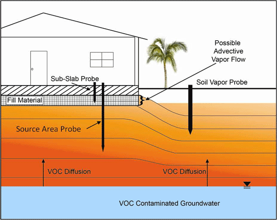
Figure 7-4: Schematic of Soil Vapor Concentration Profile. VOCs volatilize out of a groundwater plume and diffuse vertically toward the surface. Vapor phase concentrations are highest at the groundwater-vadose zone interface and decrease with decreasing depth. Vapors can accumulate under buildings or paved areas as the ability to diffuse outward and be emitted to the atmosphere becomes limited or as anaerobic conditions develop due to insufficient replenishment of oxygen.
Small-volume point samples are used during the initial phase of investigation to identify large-scale vapor plume patterns and initially estimate potential vapor intrusion risks to overlying, existing, or future buildings. A relatively small number of soil vapor samples (e.g., three to ten) are typically used to initially identify the presence or absence of potential subsurface VOC source areas. Samples are typically collected from within suspect soil source areas or immediately above suspect groundwater sources. The additional collection of soil vapor samples from the fill material immediately under the building slab is recommended for initial site characterization at sites where the distance to the source area is greater than 5 feet (see Section 7.6.2.3). This will provide information on the upward attenuation of VOCs away from a source area. (Note that reliable correlation between vapor points will be limited by uncertainty regarding the magnitude of random, small-scale variability within the vapor plume). Confirmation of the plume boundaries based on multiple points is necessary to avoid false negatives and under estimation of the overall plume size. The location and shape of a vapor plume might not mimic the shape of the primary source area (i.e., contaminated soil or groundwater). This is because the outward, lateral migration of vapors away from the source area is strongly influenced by small-scale heterogeneities in the soil and associated preferential pathways that may not be obvious in the field. In the experience of the HEER Office, high concentration areas of vapor plumes can be located some distance from the primary source area, complicating identification of the latter based on soil vapor data alone.
Locations for soil vapor sampling should be selected based on the objectives of the investigation. If the objective is to identify and map large-scale vapor plume patterns, then strategically located sampling points over and around the suspected source area are appropriate, with samples collected at similar depths or targeted to suspected preferential pathways. Samples collected directly within a suspect vadose-zone source area or immediately above a groundwater source can be useful for evaluating the strength of the source. Lateral spacing between sample locations should take into consideration subsurface utilities, building foundations, or planned future use of the site. Care should be taken to avoid utilities when collecting vapor samples within or nearby utility corridors.
If the objective of the investigation is to assess potential vapor intrusion impacts at an existing building, then targeted sampling locations at the building, at the vapor source, and possibly in-between may be appropriate. Grids of passive soil vapor samples should also be considered (see Section 7.8.3 and see Section 7.12). The collection of small-volume soil vapor samples from immediately beneath building foundations (i.e., below the concrete slab or within crawl spaces) can also assist in subsequent designation of LVP subslab vapor points for more direct assessment of potential vapor intrusion risk (Section 7.8.5). For example, LVP samples could be collected directly within high-concentration areas of a plume in order to assess worst-case, vapor intrusion conditions. In contrast, LVP samples might be collected from localized, low-concentration areas within a plume suspected to indicate active vapor intrusion, as less-impacted air is advectively drawn into this area of the plume.
Note that dry soil under slabs can serve to enhance vapor concentrations in comparison to soils with a higher moisture content, even though the total concentration/mass of VOCs in both scenarios is similar (USEPA 2012d). Small- and/or large-volume samples from utility corridors may be warranted, since coarse fill in the trenches can serve as a conduit for vapors to the slab as well as to utility penetrations and other potential preferential pathways through the floor and into the building (see also USEPA 2012d). Sample collection adjacent to buildings can be considered if the source of contamination is not below the building or the collection of vapor samples directly beneath the building is limited due access issues or the presence of subsurface utilities. If this is the case then samples should be conservatively collected from a depth of five to ten feet below ground surface (or no more than two to three feet above groundwater for shallow water tables) in order to take into consideration the potential buildup of vapors under existing or future building slabs.
Small-volume soil vapor sample data for in situ characterization of a subslab vapor plume can be collected above suspect sources areas beneath the building slab, in the vicinity of utility corridors that could serve as preferential pathways for vapor migration, beneath high-risk areas of the building based on use or penetrations in the slab or, in the absence of other information, from the center of the building slab (USEPA 2012d; CalEPA 2011; see Section 7.7.2). Vapor points also should be placed in the vicinity of the building where vapor intrusion is considered to be most likely, as well as between the center of the building and adjacent sources that do not directly underlie the building (see Subsection 7.7.2).The number of probes that can be installed for in situ characterization of a vapor plume will in part be limited by cost and logistical considerations, including accessibility of locations for sample collection and the presence of subslab utilities.
As discussed above, the type of chemicals present in the soil vapor should also be considered in selecting soil vapor sampling locations. Biodegradation can play an important role in the subsurface migration of petroleum-related contaminants and can significantly reduce the concentration of VOCs in vapors over short distances. At sites where the chemicals of concern are chlorinated compounds (e.g., dry cleaner sites), however, biodegradation is unlikely to be an important process, and elevated concentrations of VOCs can persist for significant distances. Elevated concentrations of VOCs in soil vapors can also persist for long periods of time in the vadose zone following active, in situ remediation of contaminated groundwater (“residual vapor plume,” see Table 7-1). The San Diego County Site Assessment and Mitigation (SAM) Manual, among other references, provides a useful source of soil vapor sampling strategies for a variety of site scenarios (SDC 2011).
7.6.2.3 SOIL VAPOR SAMPLE DEPTHS AND DEPTH INTERVALS
The depth of soil vapor points depends on the objectives of the investigation (Figure 7-4). Characterization of known or suspected source areas should consider such factors as the nature and magnitude of the release, the subsurface geology and the depth to groundwater. The investigation of potential vapor intrusion hazards will require the placement of sample points within shallow, vapor flow pathways, including utility trenches and fill material immediately beneath slabs (e.g., first 6 to 12 inches of soil beneath building slab).
Ideally, the lateral and vertical extent of vapor plumes should be delineated to HDOH Tier 1 soil vapor action levels applicable to residential land use (HDOH, 2016). Small-volume sample data are currently most appropriate to accomplish this task, due to limitations on the collection of LVP samples from deeper soil or from open, uncapped areas and the potential for breakthrough to outdoor air. Less conservative soil vapor action levels may be appropriate for assessment of vapor intrusion risk at commercial/industrial sites. Failure to compare site data to residential action levels may impose the need for a land use restriction on the site, however.
The collection of small-volume vapor samples and/or LVP samples from the fill material immediately beneath a building slab (e.g., first 6 to 12 inches of soil) is an important part of a vapor intrusion investigation. Relatively permeable, sandy silts are typically used as fill material under building slabs to provide structural stability. This fill material is often more permeable to vapors than the native, clayey soils in Hawaiʻi and can serve as a preferential pathway for subsurface vapors via connecting utility trenches or other conduits.
Soil vapor samples should therefore always be collected in the fill material immediately beneath the slab for evaluation of current vapor intrusion hazards, even if deeper samples are also collected. A focus on deeper soil vapor sample data can be misleading, since the samples do not take into account upward attenuation from the source area (especially important for petroleum). Deeper data could also miss contamination that is restricted to the fill material immediately beneath the building slab associated with indoor spills of solvents and other VOCs and downward migration through the floor or through broken drain pipes. Underlying soils might be relatively un-impacted, even though the concentrations of VOCs in vapors within the fill material are extremely high. This is a common scenario for dry cleaners, where high levels of PCE and related VOCs may be detected in subslab soil gas but not in deeper soil samples (or even soil samples collected from under the slab)
The presence of a building slab or other paving also significantly slows, or prevents, soil vapor from diffusing upwards and escaping to the atmosphere. This can result in elevated soil vapor VOC concentrations beneath the slab/paving in comparison to adjacent, uncovered areas. Note, however, that diffusive VOC transport can never lead to higher concentrations under the slab than at the source.
The collection of soil vapor samples from both the fill material immediately under the building slab and the suspected or known source area is recommended at sites where the distance to the source area is 5 feet or greater, but no closer than 2-3 ft to the water table to avoid pulling water into the sample collection device (see Figure 7-4; see also Sections 7.9.3 and 7.10.1). Small-volume sample data can be used to assess large-scale, vapor plume patterns. The collection of LVP sample data is recommended for more direct assessment of vapor intrusion risk (Section 7.8.5). This will help assess the need to seal cracks and utility gaps in the building floor as an added measure of precaution, in the event that nearby portions of the vapor plume exceed subslab soil vapor action levels, even though the measured concentrations of volatile chemicals in actual soil vapor do not, and potential preferential pathways into the building were overlooked (se Section 7.14.1). As discussed below, in cases where the extent and magnitude of contamination is relatively small, the site could still receive case closure without further monitoring or action (see also HDOH 2007c). In other cases additional monitoring to verify that adverse, vapor intrusion impacts are unlikely to occur will be needed (see Section 7.10.1). This will typically require the periodic collection of LVP vapor samples beneath targeted areas of the slab, similar to the collection of periodic samples from groundwater monitoring wells. Reliance on small-volume samples might, however, be required for monitoring of vapors beneath building slabs that cannot be sufficiently sealed for LVP sample collection. The collection of LVP data likewise might not be feasible for sites with low-permeability soil immediately beneath the building slab, although this would likewise reduce the risk of advective flow of vapors into the building.
Collection depths for small-volume sample data to be used to assess vapor intrusion risk in open areas where LVP sample data are not practical depends in part on the VOCs present. At sites with recalcitrant compounds (e.g. chlorinated solvents) soil vapor samples should be collected from no less than five feet below ground surface. Soil vapor samples collected from depths of less than five feet can underestimate the concentrations of recalcitrant compounds that could accumulate if a building were present. Soil vapor samples should be collected from a minimum depth of ten feet for petroleum-contaminated sites or no more than two to three feet above groundwater for sites with a shallow water table. This is necessary in order to take into consideration the potential buildup of vapors under existing or future building slabs due to low-oxygen conditions and a reduced potential for biodegradation.
Additional sample depths will depend on site-specific conditions and the investigation focus. In some cases it may also be desirable to assess the vertical distribution of vapor-phase contaminants between the source media and the ground surface or the foundation of a building. This will require the collection of samples from a minimum of two depths, typically one within or immediately above the source and one at the target receptor point. Three or more sample depths may be beneficial at sites with deep sources or water tables.
The site geology should also be considered when identifying sampling depths. In general, installation of vapor sampling probes in relatively high permeability horizons is preferred; however, the overall CSM should be taken into account as well. Permanent soil vapor probes should be installed above the maximum-anticipated, seasonally- or tidally-influenced elevation of the water table.
7.6.2.4 SOIL VAPOR SAMPLE SCREEN INTERVALS
Screens used for subslab samples should match the thickness of permeable, fill material immediately beneath the slab, typically four to six inches. Both small-volume and LVP vapor samples are typically collected though a temporary or permanent six-inch (15cm) screen or “implant.” The length and placement of the screen depends on the investigation objectives. Longer screening might be warranted for more reliable characterization of large-scale, vapor plume patterns. As discussed above and in Section 7.8.5, data for small volumes of vapor can be useful for identification of large-scale plume patterns but are not necessarily pertinent to assessment of vapor intrusion. This is similar to issues related to the use of discrete sample data for very general screening purposes versus the use of “large-mass,” Multi Increment soil sample data to more directly evaluate risk.
Six- to twelve-inch vapor point screens are generally desirable for characterization of subslab vapors, since HDOH soil vapor action levels are intended to apply to vapors within the assumed narrow, advective zone in the immediate vicinity of a vapor entry point. Much longer screens might be desirable for in situ, larger-scale characterization of deeper portions of a vapor plume. For example, a five-foot (1.5m) length of a two inch-diameter (15 cm) well screen contains approximately 30 liters of air. Allowing the air inside of the well screen to equilibrate with vapors in the surrounding soil would allow a sample collected from the well screen to represent a much larger volume of vapor than the vapor actually captured within a canister. The resulting data would provide a more reliable and reproducible characterization of the plume at that specific location in terms of vapor intrusion risk. Replicate samples could be collected over time to assess data precision and temporal variability within the vapor plume.
Note that the same is true with respect to the representativeness of a groundwater sample collected from a five-foot, monitoring well screen or from a much smaller interval using grab samples or passive diffusion bags (see Section 6). Additional guidance on this topic, including the concept of “Decision Units” for the collection or groundwater sample data will be incorporated into Section 6 of this guidance document in the future.
7.7 INDOOR AIR SAMPLING STRATEGIES
7.7.1 DETERMINING WHEN TO COLLECT INDOOR AIR SAMPLES
Although counterintuitive, testing of indoor air to identify and evaluate potential vapor intrusion concerns is fraught with potential error and generally discouraged except in cases where subslab soil vapor data indicate a clear threat to indoor air (see HDOH, 2016). This is due to the common presence of the same suite of targeted VOCs in soil vapor in indoor air from sources within or outside of the building (e.g., USEPA 2011e).
As noted in Table 7-2, background levels of VOCs in indoor air from indoor sources exceed conservative action levels for many common chemicals. Correlation of indoor air data with subsurface, soil vapor data can therefore be difficult if not impossible if the concentration of VOCs identified in indoor air falls within the range of anticipated background. Although precautionary measures could be taken to mitigate potential vapor intrusion (e.g., sealing of floors, improved ventilation, etc.), as a general rule a home or building should not be flagged for potential vapor intrusion hazards unless this is supported by multiple lines of evidence, including indoor air data well above anticipated, background levels. This is discussed further in Section 7.14.2.
The presence and concentration of contaminants in indoor air is influenced by several factors, including the following: (1) the input rate of the contaminant from the source, (2) degree of ventilation and air exchange in the building, and (3) the input rate of other sources within or near the building (i.e., from outdoor air and not the subsurface). Assessments of vapor intrusion should consider the following factors:
Table 7-2 Comparison of HEER Indoor Air Action Levels to Typical Indoor Air Concentrations of Common VOCs.
| Volatile Chemical | 1HEER Indoor Air Action Level (ug/m³) | 2Range of Background Indoor Air Concentrations |
| Benzene | 0.31 | <RL-4.7 |
| Ethylbenzene | 0.97 | 1–3.7 |
| Toluene | 1,000 | 4.8–24 |
| Xylenes | 21 | 2.6-17.6 |
| 3Naphthalene | 0.057 | 0.18-1.7 |
| 4,5Total Petroleum Hydrocarbons | 131 | 116-594 |
| Tetrachloroethene | 0.41 | <RL–2.2 |
| Trichloroethene | 1.2 | <RL–1.1 |
- HDOH, 2016; residential indoor air action level noted.
- USEPA 2011b; Range of 50th percentile noted (<RL = less than laboratory reporting limit).
- Jia and Batterman 2010; urban houses.
- HDOH, 2016; indoor action level equal to sum of vapor-phase, TPH aliphatic and aromatic compounds (see Section 7.11).
- MADEP 2008; range TPH 50th to 90th percentile.
- Indoor air sources (other than soil vapor);
- Outdoor air sources (other than soil vapor);
- Location and characteristics of known or suspected soil vapor source;
- Building ventilation and air exchange rate;
- Building materials and condition.
A number of commonly used household products contain some of the same compounds of concern as targeted in vapor intrusion investigations (e.g., TPH and BTEX from cleaners and fuels, PCE from dry-cleaned clothes, TCE and TCA from degreasing solvents, etc.,). Common sources of VOCs in indoor air include (USEPA 2011e, ITRC 2007, HDOH, 2016):
Building Materials:
- Carpets and adhesives;
- Composite wood products
- Plastics;
- Paints;
- Sealing caulks;
- Parts cleaning solvents;
- Upholstery fabrics;
- Varnishes;
- Vinyl and linoleum floors;
- Polyester resins and epoxies;
Home and Personal Care Products:
- Air fresheners;
- Air cleaners;
- Cleaning and disinfection products;
- Cosmetics;
- Fuel oil and gasoline;
- Mothballs;
- Running automobiles, generators or lawn equipment;
Behaviors:
- Smoking;
- Dry cleaning;
- Hobbies that involve glues;
- Newspapers;
- Non-electric space heaters;
- Photocopiers;
- Stored paints and chemicals.
In some areas, especially urban centers, TPH, benzene and related contaminants associated with auto exhaust in outdoor air can also exceed conservative, indoor air action levels.
For these reasons, testing of indoor air to evaluate potential vapor intrusion impacts is generally discouraged unless concentrations of targeted chemicals in subslab soil vapor are more than one-thousand times typical indoor air concentrations for residences and two-thousand times typical indoor air concentrations for commercial/industrial buildings (assumed indoor air:subslab soil gas attenuation factors; see Subsections 7.3, 7.14 and Table 7-2; see also HDOH, 2016). Indoor air sampling may also be warranted if field screening of potential vapor pathways inside of a building suggest that vapors could be impacting indoor air at levels significantly above background and the pathways are unlikely to be sealed in the absence of indoor data to support such actions (e.g., PID readings around utility gaps in floors, drains, wall sockets, etc.; see Section 7.7.2; see also MADEP 2002b, CalEPA 2011, New York State DOH 2006).
The evaluation of potential vapor intrusion hazards and decisions regarding the need for remedial actions will instead, in most cases, focus on subslab or crawl space data. Shallow soil vapor data or data for samples collected under paved areas can be taken into consideration for sites without existing buildings.
Subslab (including sub-basement) soil vapor samples should be collected for buildings with a slab-on-grade construction. For buildings with a crawl space design, shallow soil vapor samples should be collected adjacent to the building in addition to samples from the crawl space. In both cases, it is preferable that soil vapor and/or crawl space samples be collected prior to collection of indoor air samples and used to determine the need to collect the latter (see HDOH 2016). If a significant source of potential vapors is present below the building (e.g., petroleum free product on shallow groundwater) then the collection of source area soil vapor samples is also recommended (see Subsections 7.6.2). Together, subslab and source area data should be reviewed to determine the need for the collection of indoor air samples.
If indoor air sampling is still desired or required, then sample collection and interpretation of data should be carried out under the direction and oversight of HDOH. Soil vapor (or crawl space) samples should be collected at the same time in order to assist in the interpretation of the indoor air data (see Subsection 7.14). Indoor air data should never be used as the only line of evidence for vapor intrusion.
Indoor air data should be compared to both risk-based screening levels and anticipated background concentrations. More than one round of sampling is recommended if a significant source of vapors is identified beneath a building (see Subsection 7.11.3). If representative concentrations of targeted VOCs fall within the range of anticipated background concentrations then active measures to address vapor intrusion are not necessary (see Section 7.14.2) , although sealing of cracks and gaps in floors should be carried out as a precautionary measure (see Section 7.14.1).
7.7.2 INDOOR AIR SAMPLING DESIGN
Specific guidance regarding the location, duration, and frequency of indoor air sampling is provided in Section 7.11. The following factors will influence an indoor air quality sampling strategy:
- Sources: All of the potential sources of indoor air contamination should be considered in developing a sampling plan. Sources can include, but are not limited to, subsurface contamination (i.e., vapor intrusion), indoor sources (i.e., use/storage of VOC containing chemicals), and outdoor background sources (i.e., VOCs in the ambient background air around a building).
- Pathways: Likely or potential pathways for VOCs to enter the building air should be considered in developing a sampling strategy. Common pathways for vapor intrusion from the subsurface are cracks or utility penetrations through the slab or basement walls/floor, sumps with earthen floors, and drain pipes. Elevator shafts could also serve as pathways for vapor intrusion, although these structures tend to mimic chimneys by conducting air out of rather than into buildings, including vapors that might intrude into the bottom area of the shaft. Bathrooms, kitchens and utility rooms are often the primary entry points for intruding vapors. VOCs can also enter a building through the heating, ventilation, and air conditioning (HVAC) system intake if the ambient air contains VOCs (if a VOC source is located upwind of the HVAC intake, higher concentrations of VOCs can be introduced to the indoor air than would be expected based on the general ambient air conditions around the building). Most buildings have indoor sources of VOCs– these should be carefully evaluated and, if possible, removed prior to sampling.
- Heating, Ventilating, and Air Conditioning: Operating conditions of the HVAC system can have a significant effect on VOC concentrations over a short time frame (see Section 7.1). The concentration of VOCs will generally be lowest when the HVAC air conditioning system is operating, due to the inflow of fresh air, dilution of vapors from indoor sources and the reduction of subsurface vapor intrusion when the building is over pressurized. Indoor air quality will be lowest when the HVAC system is not operating, due to the lack of fresh air entering the building to offset VOC emissions from furniture, plastics, glue and other indoor sources as well as the potential for the building to become under-pressured due (at least in Hawaiʻi) to outside wind effects that could induce an upward flow of subsurface vapors.
- Occupants: The presence and activities of building occupants can have a significant effect on VOC concentrations in indoor air. For example, freshly dry-cleaned clothing can introduce PCE to the indoor air, and smoking can release a variety of VOCs including benzene. Opening of doors and windows can increase the building air exchange rate and thereby lower VOC concentrations (assuming that higher concentrations are not present in outdoor air).
To prevent, investigate, and resolve indoor air quality problems, it is important to understand the role each of these factors can play.
The indoor air sampling strategy should identify the location, duration, and frequency of indoor air sampling. As with soil vapor sampling strategy, location, duration, and frequency will be influenced by site-specific conditions and the study objective. For example, if the goal of the study is to obtain a representative estimate of the average concentration of contaminants in indoor air that could present potential risk to the occupants of a building, then several indoor air samples should be collected in various portions of the occupied space and weighted accordingly. If the goal of the study is to measure the highest concentration to which an occupant might be exposed, then sampling could be conducted in the area closest to the suspected source or pathway for contamination (MADEP 2002b).
7.8 SAMPLING APPROACHES AND EQUIPMENT
The collection of soil vapor or indoor air samples can be more involved and complex than soil or groundwater sample collection. This is due in part to the need for special sampling equipment and containers to address the reactivity of vapor-phase chemicals and the need to prevent leaks during sample collection.
Based on the type of sampling equipment and containers, soil vapor or indoor air sampling approaches can be grouped into the following categories: (1) whole air sampling; (2) sorbent tube sampling; (3) passive sampling using sorbent materials; and (4) flux chamber sampling. The first two methods are often referred to as active sampling (see Hartman 2002). Whole air sampling involves collecting a volume of gas in a sample container, such as a Summa canister or a Tedlar bag, and analyzing the gas from that container directly. The concentration of targeted compounds is directly reported.
Sorbent tube sampling involves drawing a specified volume of soil vapor or indoor air through a sorbent material using a pump or other vacuum source and analyzing the sorbent material. The concentration of a targeted compound in the media tested is calculated by dividing the mass of the compounds collected on the sorbent material by the volume of vapor or air drawn through the sampler. If reanalysis of a sample might be required, then a collection method that relies on extraction of the sample (e.g., sorbent tubes) rather than purging (e.g., Summa canister) should be considered. The ability to reanalyze a sample collected in a Summa canister is limited due to the fixed volume collected versus the volume required for a specific analytical method. This should be discussed in more detail with the laboratory as needed.
Passive sampling methods rely on the placement of a sorbent material at a sample location for a period of time. The mass of a targeted compound collected on the sampler is then measured. Flux chambers are traditionally used to measure vapor emission rates from point sources such as waste ponds. Their use in soil vapor investigations is more limited but in some instances can be beneficial. A comparison of the key advantages and disadvantages to each of these approaches is provided in Table 7-3.
Similar to soil and groundwater sample collection, a combination of sampling approaches can be used if analyzing for a broad range of chemical compounds. For example, relatively inexpensive passive sampling can be used to initially screen a site for shallow vapor plumes and assist in the identification of areas for active soil vapor sampling. For the investigation of vapors associated with releases of diesel and other middle distillate fuels, a combined used of both Summa canisters and sorbent tubes is recommended (see Subsection 7.13.1.2). Data from Summa canister samples can be used to determine concentrations of individual VOC and short-range TPH compounds (e.g., <C12 aliphatics). Sorbent tube samples can be collected to evaluate longer range TPH compounds and semi-volatile organic compounds (SVOCs).
Each of these methods is discussed in more detail in the following sections. Consultation with the analytical laboratory to discuss specific standard operating procedures and sampling methods is strongly recommended during the planning phase for each project requiring the collection of soil vapor or indoor air samples.
Equipment that could come in contact with a vapor sample should be cleaned or decontaminated between samples to avoid cross contamination by trace levels of contaminants. Summa canisters and sorbent tubes should be certified clean by the laboratory. Used tubing should be disposed of. Reuse of Swageloks and ferrules between samples is discouraged. This is primarily a concern for the collection of outdoor or indoor air samples, where data are compared to very low action levels.
Table 7-3 Comparison of Soil Vapor & Indoor Air Sampling Approaches
| Sampling Approach | Container/ Equipment | Advantages | Disadvantages |
| Active | Summa Canister | Familiar, widely accepted, rugged, no pump required (vacuum), excellent inert surface, low detection levels (ppbv), up to 30-day hold time from time of sample collection, easily air-shipped | Cost, bulky in field, slower fill time, fixed volume, collection of VOCs over restricted volatility range |
| Tedlar Bag | Inexpensive, availability, easily transported, rapidly filled | Less rugged, fixed volume, requires additional collection equipment, inner surface may sorb VOCs, medium detection levels (ppmv), short holding time, not recommended for air shipping | |
| Sorbent Tube | Large-volume samples possible, collection of VOCs over a larger volatility range, low detection levels (ppbv), up to 40-day hold time (extraction within seven days of sample collection), easily transported and air shipped | Cost, requires additional collection equipment, saturation of tubes possible, sorbent media varies with respect to VOC and anticipated VOC concentration, tubes require storage at 4°C | |
| Passive | Sorbent | Cost, ease of use, multiple samplers can be combined for analysis, long sampling times | Cannot directly measure vapor concentration |
| Water | Estimation of vapor concentrations possible, multiple samplers can be combined for analysis, long sampling times | Currently costly to install, cannot directly measure vapor concentration | |
| Flux Chamber | Flux Chamber | Measures VOC flux at surface | Does not measure in-situ concentrations, identification of vapor emission points difficult |
Table 7-4 Common Soil Vapor Concentration Unit Conversion Factors
|
Units |
Convert to: |
Multiply By: |
| μg/L | μg/m³ | 1,000 |
| mg/m³ | μg/m³ | 1,000 |
| ppmv | ppbv | 1,000 |
| ppbv | μg/m³ | MW/24 |
| μg/m³ | ppbv | 24/MW |
| ppbv | ppmv | 0.001 |
Definitions:
MW – molecular weight
mg/m3 – milligrams per cubic meter
μg/m3 – micrograms per cubic meter
μg/L – micrograms per liter
ppbv – parts per billion by volume
ppmv – parts per million by volume
FTC Funding
The FTC initiative will be funded completely through cost recovery. HDOH will implement a cost recovery process consistent with cost recovery provisions of HRS 128D-5. The cost recovery framework, including hourly rates for HDOH review and consultation services, a fee schedule, estimated total hours for review services, and justification of rates, will be developed by HDOH and communicated to the public by June 30, 2009.
Sites entering FTC prior to June 30, 2009, will be provided HDOH oversight and consultation services at no cost through that date. Sites that have entered into but not completed FTC at that date will be given 60 days notice of the initiation of cost recovery. Applications received after June 30, 2009, will require a fee/deposit in order to initiate the process.
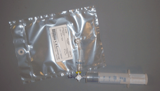
Figure 7-8: One-liter Tedlar Bag with Disposable Syringe and Three-way Valve for Filling.
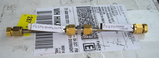
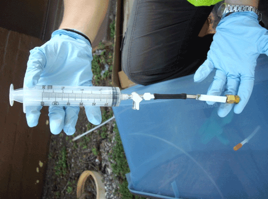
Figure 7-9: Sorbent Tubes. Upper photo: Sorbent tubes connected in series with a union fitting. Lower photo: Single sorbent tube connected to a 60ml syringe for collection of vapor sample (see also Figure 7-27).
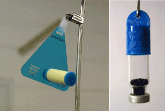
Figure 7-11: Two Examples of Indoor Air Passive Sample Collectors.
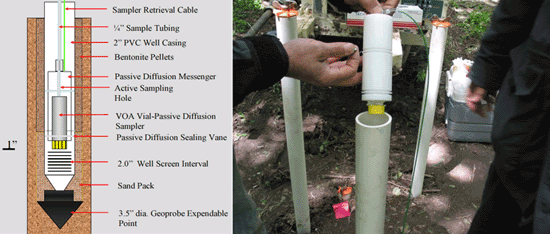
Figure 7-12: Passive Diffusion Sampler (PDS). Schematic of sampler on left and photo of a sampler being installed on the right.
Table 7-5 Comparison of TCE and PCE Results for Passive Diffusion Sampler and Active Soil Vapor Sample
| Location | TCE Results | PCE Results | ||||
| Mean PDS | Mean Active | PDS/Active Percentage | Mean PDS | Mean Active | PDS/Active Percentage | |
| 1 | 4,536 | 6,500 | 70% | ND | ND | ND |
| 2 | 27,584 | 16,000 | 172% | 384 | 300 | 128% |
| 3 | 56,001 | 20,000 | 280% | 752 | 285 | 264% |
| 4 | 41,073 | 25,000 | 164% | 744 | 385 | 193% |
| 5 | 466 | 190 | 245% | ND | ND | ND |
| 6 | 3,283 | 550 | 597% | ND | ND | ND |
| 7 | 5,234 | 2,000 | 262% | ND | ND | ND |
| 8 | 1,970 | 1,900 | 104% | ND | ND | ND |
| 9 | 503 | 440 | 114% | ND | ND | ND |
| 10 | 482 | 1,500 | 321% | ND | ND | ND |
| Average | 233% | 195% | ||||
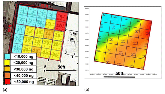
Figure 7-13 Summary of high-density, passive sampler data for PCE vapors beneath the slab of a former dry cleaner: a) True data resolution based on PCE mass reported for each grid cell; (b) Extrapolated isopleth map based on assignment of data to center point of grid cell and use of contouring program.
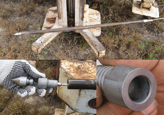
Figure 7-14. Designation of soil vapor DU beneath a building slab for collection of LVP samples; recommended default DU volume of 3,000 liters represents the default, daily vapor entry rate used to develop HDOH (2017a) soil vapor action levels for vapor intrusion risk.
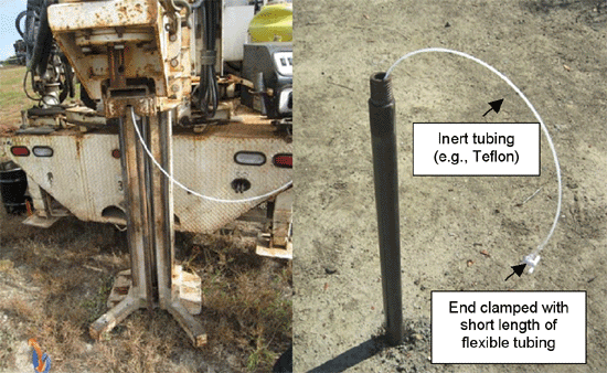
Figure 7-15. Example options for designation of purge points for collection of LVP subslab vapor samples: A) High-risk occupancy room within building; B) Subslab utility trench and preferential pathway; C) High-concentration area based on result of small-volume vapor sample data; D) Center of slab.
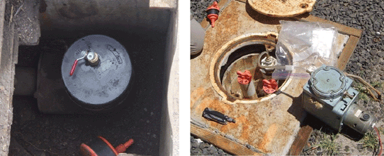
Figure 7-16. Floor drain and suspect deep cracks sealed with bentonite slurry to minimize downward leakage of indoor air into purge point during LVP sample collection.
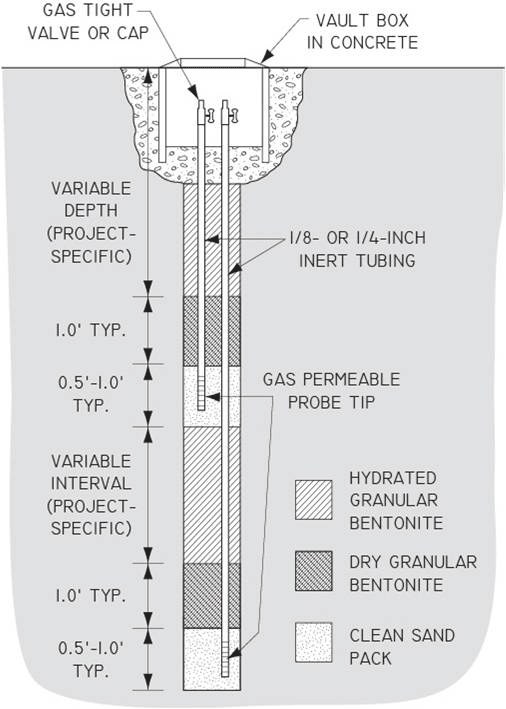
Figure 7-17. Simplified schematic of Large Volume Purge sampling train.
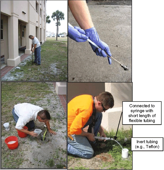
Figure 7-18. Example design of LVP sample collection system.
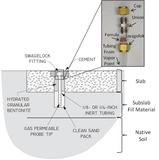
Figure 7-19. Installation of LVP vapor extraction point used in HDOH (2017c) field study: a) Circular saw used to cut eight-inch hole in concrete for installation of vapor point and protective casing (latter not normally included); b) Completed hole; c) Two-inch PVC vapor point; d) Completed vapor point (interior sealed with cement grout). A smaller diameter hole will normally be adequate for a two-inch soil vapor point.
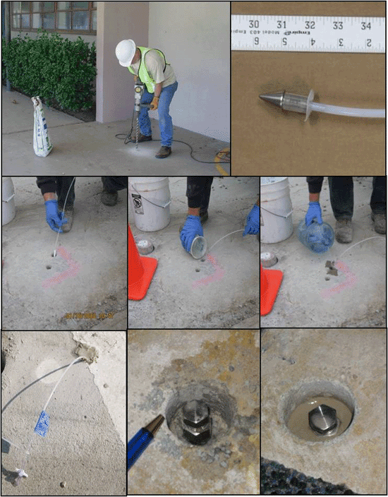
Figure 7-20. Example, completed field LVP sample collection set up (HDOH 2017c; Shop-Vac pump not shown).
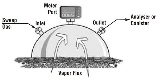
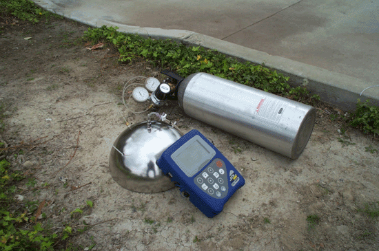
Figure 7-21: Schematic Diagram and Photograph of Flux Chamber
7.8.1 WHOLE AIR SAMPLING
Whole air samples are typically collected in Summa canisters when definitive data with low detection levels are required; however other containers such as Tedlar bags, gas-tight vials, and syringes are also suitable for some applications. Low detection levels can also be obtained using sorbent tubes and TO-17 analytical methods, although the volume of air or vapor drawn through the tubes is limited by the sorptive capacity of the media used. Individual laboratories often publish guidance on the use of various whole-air methods (e.g., Air Toxics 2012). Whole air sampling (or other active soil vapor sampling) is recommended to quantify concentrations of vapor-phase chemicals for an exposure or risk assessment. Contaminant concentrations can be quantified in units of volume of gas per unit volume of air (e.g., parts per million by volume [ppmv] or part per billion by volume [ppbv]) or in units of mass per unit volume (e.g., milligrams per liter [mg/L] or micrograms per cubic meter [µg/m³]). Concentrations should be reported in units of µg/m³ for comparison to HDOH EALs.
It is important to note that unlike aqueous samples, volume units are not equivalent to mass units for gaseous samples. The molecular weight of the analyte and the temperature and pressure of the sample must be used to convert from volume units to mass units. The conversion can be achieved using the Ideal Gas Law equation. The following equation simplifies the Ideal Gas Law equation assuming atmospheric pressure (one atmosphere = 760 millimeters of mercury [mm Hg]) and standard room temperature of 298 Kelvin (K) (25 degrees Celsius [° C]):
| µg/m³ = | (ppbv x MW)/24.45 |
| Where: | |
| ppbv = | parts per billion by volume |
| µg/m³ = | micrograms per cubic meter |
| MW = | Molecular Weight (chemical-specific) |
Table 7-4 presents other common unit conversion factors and HDOH has developed a Vapor Unit Conversion spreadsheet that converts between concentrations and is available for download from the EHE web page (HDOH 2016).
See Table H in Appendix 1 of the HDOH EHE guidance for the molecular weight of common chemicals (HDOH, 2016). In general, target compounds conducive to whole air sampling are chemically stable and have a vapor pressure greater than 0.1 torr at 25 ˚ C and 760 millimeters of mercury (one atmosphere). Effective recovery of chemicals from active soil vapor samples depends on sample humidity, chemical activity of the sample matrix, and the sample container’s degree of inertness.
7.8.1.1 SUMMA CANISTERS
A Summa canister is a stainless steel container that is placed under a vacuum and then used to collect a soil vapor or air sample. The canister is cleaned internally using electropolishing and chemical deactivation to produce an interior surface that is nearly chemically inert. This minimizes reactions with the vapor sample and maximizes recovery of volatile compounds from the container. Recovery is generally limited to chemicals with up to ten carbon molecules for aromatic compounds, however, including naphthalene, and up to twelve carbon molecules for aliphatic compounds.
Figure 7-5 Summa Canisters (spherical and cylindrical containers) with Flow Controllers (smaller gauges and blue box).
Summa canister volumes range from 400 milliliters (ml) to 6 liters, with one-liter and six-liter canisters being most commonly deployed in the field (Figures 7-5 & 7-6). Larger canisters provide more sample volume for the laboratory and allow for lower detection levels. For indoor or outdoor air sampling, six-liter canisters are typically most appropriate as they support the low detection levels necessary for risk assessment or screening against indoor air standards. They are also better suited to collecting time-integrated samples (e.g., eight to twenty four-hours). Smaller canisters are typically used for soil vapor samples, for which screening levels are typically several orders of magnitude higher than for indoor air. Collection of vapor samples greater than one-liter can be problematic as well as time consuming at sites with relatively tight soils. HDOH recommends a minimum sample size of one-liter for soil vapor samples in order to assist in the collection of data that are representative of the site being investigated. HDOH further recommends the use of Summa canister data and/or sorbent tube data (provided a minimum one-liter sample is drawn) for final decision making purposes.
General procedures when planning a soil vapor investigation using Summa canisters include:
- Obtain the field equipment checklist and inventory equipment and materials needed for the soil investigation before proceeding to rent, obtain and stage all equipment
- Order clean-certified Summas and related equipment from the laboratory based on the number of samples to be collected plus a minimum of one extra canister and flow controller. Ideally this should be done by two weeks before the scheduled field work in order to give the laboratory adequate time to prepare the canisters and ship them to Hawaiʻi.
- Check the vacuum of all the canisters as soon as they arrive. Use the pressure gauge the lab sends with the canister. If more than one gauge is sent, use the same gauge to check the canisters before and after sampling in order to ensure consistency. Record the date, time and readings on both the canister tags and field forms. Vacuum readings should be approximately 30 inches of mercury. Consider rejection any canisters that differ from others by three inches of mercury or more.
Summa canisters should be certified clean by the analytical laboratory that supplies them. The laboratory cleans the Summa canisters after each use. The cleaning process is certified by filling a canister with a clean gas (e.g., nitrogen) and then analyzing the gas using method TO-14 or TO-15. Canisters are typically either batch certified or individually certified. For batch certification, a portion of canisters from a cleaning batch is tested (e.g., 10%). For individual or 100% certification, each individual canister is tested.
The Summa canister is prepared by the lab for sampling by evacuating the contents to a vacuum of approximately 30 inches of mercury (in Hg). This ensures that the volume of air drawn into the canister will be approximately equal to the canister volume. The vacuum in each canister should be documented prior to sampling. This can be done by attaching a separate vacuum gauge to the canister and opening the intake valve. The flow controller can also be attached then capped at the intake port and the Summa canister intake valve again opened. Doing both allows testing of the flow controller vacuum gauge for accuracy, a not-uncommon field problem.
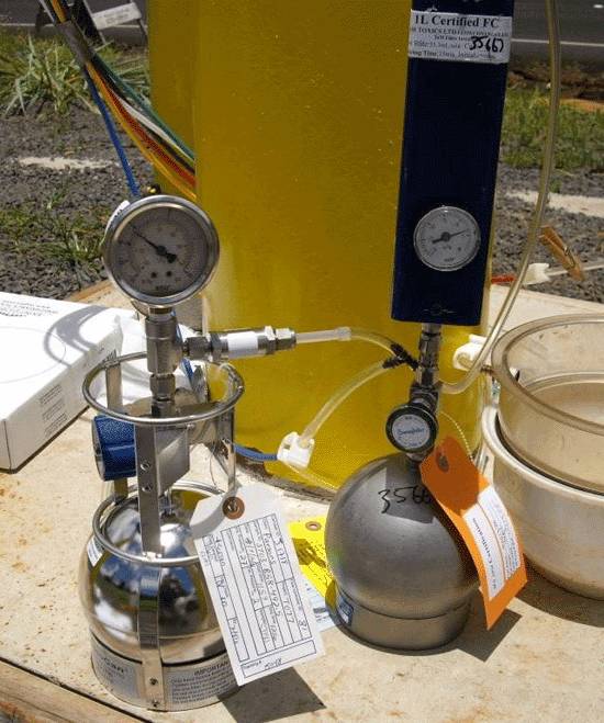
Figure 7-6 Summa Canister and Flow Controller Setups (note smaller flow controller on left).
Flow controllers (or flow restrictors) are essential equipment for the collection of vapor samples with Summa canisters. The controllers limit the rate at which a sample can be drawn into a canister and assure that the sample flow rate is appropriate for the targeted sample collection time (see Section 7.10.3). Flow controllers also help ensure that an excessive vacuum is not applied to soil. Doing so could potentially strip VOCs from free product or sorbed to soil and bias the vapor sample collected. Older flow controllers tend to be bulky, less reliable and increase the chance for leaks (e.g., see Figure 7-6). Newer flow controllers are more compact and easier to use in the field (See Figure 7-7). In some cases, they may come preset and pre-attached to the Summa canister. A vacuum gauge at the vapor collection point is used to monitor the vacuum pulled during the collection of LVP vapor samples (Section 7.8.5).
The analytical laboratory providing the Summa canisters and flow controllers should be consulted during the planning stages to ensure the appropriate size canisters and appropriately calibrated flow controllers are provided (Figure 7-7). Laboratories typically provide matched canisters and flow controllers. It is advisable to order extra canisters and flow controllers in case insufficient vacuum is present in a canister or the flow controller does not work properly.
A 10% certification of Summa canisters (i.e., 10% of canisters) is recommended for standard TO-14 or TO-15 analysis for soil vapor or other applications where very low detection levels are not required. This is appropriate for routine ambient air applications and the collection of high-concentration soil vapor and landfill gas samples where parts-per-million or parts-per-billion reporting levels are required. A 100% certification is recommended when “Low Level” or selected ion monitoring (SIM) analyses will be conducted and parts-per-trillion reporting levels are required (e.g. for indoor air). If desired, certification can usually be provided at an additional cost for specific pairs of flow controllers and canisters that are labeled as such by the laboratory.
The Summa canister valve should be closed and sample collection ceased once a residual vacuum of 3-5 inches of mercury is reached and the final vacuum recorded. This will help notify the lab of potential container leakage and compromised samples during storage and shipment. A holding time of 30 days is recommended once the sample has been collected (USEPA 1999b). Most laboratories recommend that canisters be returned within 14 days of receipt in order to help ensure the integrity of the canister and ensure that hold times are not exceeded prior to analysis.
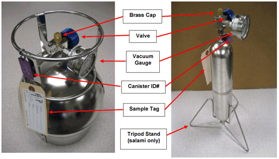
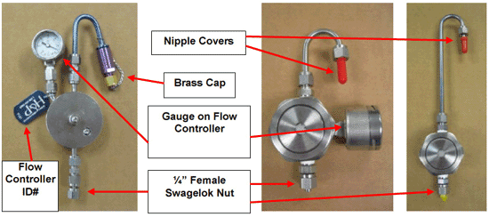
Figure 7-7: Summa Canister and Flow Controller Parts.
7.8.1.2 TEDLAR BAGS
HDOH recommends the use of Summa canisters or sorbent tubes for sample collection if the data are to be used for final, decision making purposes. Tedlar bags are flexible, plastic bags that can be used for the collection of air or vapor samples with a syringe or a lung box. Tedlar bags can offer an inexpensive, screening tool for initial site investigations or monitoring, however. A Tedlar bag is made from two layers of Tedlar film sealed at the edges and containing a valve allowing for soil vapor or indoor air sample collection using a syringe or lung box . Tedlar is a trade name for a polyvinyl fluoride film that exhibits a low permeability to gases, chemical inertness, weathering resistance, and low off-gassing. The manufacturer of Tedlar, DuPont, announced in 2009 that they would phase out support for Tedlar film in the sample bag market. As a result, true Tedlar bags are becoming more difficult to obtain and are being replaced by bags made of alternative materials.
Similar to canisters, Tedlar bags range in volume up to five liters, and can be used to collect high-concentration grab samples or ambient air samples. The Tedlar bags can be used for projects involving analysis of low concentrations of compounds, in the ppbv range; however, they are less robust and more prone to leaking and diffusion than Summa canisters. Shipment by air is generally not recommended, since a decrease in atmospheric pressure as the plane ascends can cause a Tedlar bag sample to expand and leak. If the use of Tedlar bags and shipment by air is not avoidable, then the bags should only be filled to 50% or less of their total capacity.
As described in Section 7.10.4, soil vapor or indoor air samples are collected in Tedlar bags using a lung box or a glass syringe equipped with a 3-way valve (Figure 7-8). Note that a plastic syringe is depicted in the figure. The use of glass syringes for sample collection is recommended due to the potential sorption of VOCs to plastic. Tedlar bags are normally disposed of following use to collect one sample since VOCs can absorb to the bag interior. This excludes bags used to screen for fixed gases like O₂, CO₂ and CH₄, which are not significantly sorptive.
7.8.1.3 WHOLE AIR SAMPLE HANDLING
In order to preserve the integrity of whole air samples, the following guidelines should be observed.
- Do not chill samples during storage as is common with soil and water samples.
- Sample containers should not be left in the direct sunlight.
- The maximum holding time in Summa canisters is typically 30 days from the time the canisters are initially cleaned, depending on the lab (labs often request return of canisters within 14 days of receipt).
- The maximum holding time for Tedlar bags is 24 to 72 hours after the sample has been collected, depending upon the compound (CalEPA 2012, SDC 2011).
Petroleum compounds and biogenic gases (e.g., methane, carbon dioxide) are less stable and should be analyzed within 24 hours for samples collected in Tedlar bags, while chlorinated compounds are more stable and bags can typically be held for up to 72 hours. However, as noted above, Tedlar bags are being phased out and replaced by bags made of alternative materials. Appropriate holding times vary depending on the material. Therefore, the supplier of sample bags not made of Tedlar, typically the laboratory, should be consulted regarding the appropriate holding time for the site contaminants of concern.
7.8.2 SORBENT TUBE SAMPLING
Sorbent tube sampling involves drawing a known volume of soil vapor or air through a sorbent material using a pump or other vacuum source and analyzing the sorbent material. Concentration is calculated by dividing the mass of a targeted compound by the volume of vapor or air drawn through the sampler. Photographs of sorbent tubes and sorbent tube sampling trains are provided in Figure 7-9. Individual laboratories publish guidance on the use of various sorbent methods (e.g., Air Toxics 2012b). Method TO-17 is the most common setup and analysis used for sorbent tubes (see Subsection 7.13).
Sorbent tubes are an optional method for short-chain VOCs (e.g., BTEX, PCE, TCE, etc., including naphthalene) and the most appropriate method for longer-chain, SVOCs that cannot be recovered from a Summa canister. The latter includes acenaphthene, methylnaphthalenes and other PAHs with molecular weights up to 200 but including pyrene, with a molecular weight of 202 (see HDOH, 2011b). As discussed below, sorbent tubes in combination with Summa canisters are recommended for testing of vapors associated with diesel and other middle distillate fuels if a significant (e.g., >10%) amount of longer-chain hydrocarbons could be present (e.g., >C10 aromatics or C12 aliphatics; see Section 7.13.1.2).
A variety of sorbent cartridges and pumping systems are provided by commercial vendors or laboratories. It is important to discuss the anticipated types and concentrations of target VOCs and SVOCs with the laboratory in order to optimize the type and amount of sorbent used to prepare the tubes. Sorbent tubes are typically shipped and stored chilled to 4°C but should be brought to ambient temperature prior to use in the field.
A low-flow pump or syringe is used to draw soil vapor or air through the sorbent over a pre-established time period. A maximum flow rate of 200 ml/minute is recommended in order to minimize the risk of leaks around the probe annulus as well as minimize the vacuum imposed on the soil and stripping of VOCs from the soil or free product (see Section 7.10.3). Pumps are typically used for the collection of larger volume, indoor or outdoor air samples. If a pump is used then the volume of soil vapor drawn through the tube is calculated by multiplying the average flow rate by the draw time. This will require recording and averaging the flow rate several times if it varies over collection of the sample.
Calibrated syringes that can be easily read in the field provide a more accurate estimation of the volume drawn through a sorbent tube for small-volume samples. A syringe draw time of no less than 15 seconds, for example, is recommended for a 50ml soil vapor sample. This is the maximum draw volume typically allowed by laboratories for collection of high-concentration soil vapor samples associated with petroleum in order to avoid saturation of the sorbent material in the tube and multiple dilutions at the laboratory. Note that the syringes should not be re-used between sample points to avoid potential contamination of sorbent tube media due to a high concentration breakthrough in a previously drawn sample.
The presence of very high concentrations of volatile compounds at some sites can significantly limit the volume of soil vapor that can be drawn through a sorbent tube without saturation of the sorbent material. Unlike canister samples, sorbent tubes have maximum reportable concentrations for VOCs, based on the sorptive capacity of the material used. Once this capacity is reached, breakthough will occur and true concentration of the chemical present cannot be determined. This can be addressed in part by using larger sorbent tubes, adjusting the sorptive material used and/or connecting two or more sorptive tubes in series and adding the masses of targeted VOCs captured in each tube.
Note that PIDs primarily target aromatic compounds and are not good indicators of total TPH levels in soil vapors without inclusion of a correction factor, since vapors are likely to be dominated by aliphatic compounds. This is especially important to consider for testing of aromatic-poor vapors from diesel fuel or other middle distillate fuels (refer to HEER Office petroleum vapor study; HDOH, 2012). PID readings for similar vapor concentrations from gasoline versus diesel can be significantly lower for diesel. An FID can be used to minimize this problem but they are not widely used in Hawaiʻi. An FID responds to both methane and petroleum-related compounds, but does not respond strongly to chlorinated solvents, and perhaps most important for rural or inter-island work in Hawaiʻi requires a ready supply of hydrogen. High humidity or low-oxygen environments can also extinguish the FID flame. This can be an issue for screening of subsurface vapor associated with degrading petroleum releases.
When possible, screening level Photoionization Detector (PID) data should be provided to the laboratory prior to sample collection in order to assist the lab in optimization of sorbent tube preparation. For heavily contaminated, petroleum-release sites in particular, the amount of soil vapor drawn through a sorbent tube might still be limited to volumes as small as 50ml. Smaller volumes are not recommended under any circumstances as they are unlikely to be representative of site conditions. This should be discussed with the laboratory prior to preparation of the sorbent tubes for sample collection. If necessary, a series of connected sorbent tubes can be used to collect larger-volume samples (see first photo in Figure 7-9).
If sorbent tubes are to be used in a high-concentration, soil vapor environment (e.g., to evaluate TPH in vapors associated with diesel-contaminated soil or groundwater) and the volume of vapors to be drawn is less than one liter then the concurrent collection of a one-liter or larger Summa canister sample is also recommended (see Section 7.13). The Summa canister sample should be collected first to help ensure that the vapor point is adequately purged and to improve the representativeness of the sorbent tube sample. The well point should then be closed using a valve or pinched shut (similar to the sampling train leak test), using a small length of flexible tubing to prevent the backflow of ambient air into the tubing and soil. Allow adequate time for the vacuum on the soil to dissipate with the vapor sampling point remaining closed. This could take several minutes for tight soils. The sorbent tube sampling train should then be connected, the vapor point re-opened, and the sample collected.
After the sample is drawn, the sorbent tube should be chilled to 4°C and sent to the laboratory for analysis. The concentration of a targeted chemical in the original vapor is calculated as the mass of the chemical sorbed divided by the volume of vapor drawn through the sorbent.
The storage and holding time for sorbent tubes vary depending on the sorbent material used and targeted VOCs but are typically up to 30 days after the tubes are prepared. Removal and testing of the sorbent material may be required by the laboratory within 14 days of sample collection for some methods.
Concurrent PID data should be provided to the laboratory in order to determine if dilution of sample is necessary prior to analysis and help reduce analytical time and costs. Note that petroleum vapors are dominated by aliphatic compounds. PIDs primarily target aromatic compounds and are not good indicators of total TPH levels in soil vapors without inclusion of a correction factor. This is especially important to remember for aromatic-poor vapors from diesel fuel or other middle distillate fuels (refer to HEER Office petroleum vapor study; HDOH, 2012). PID readings for similar vapor concentrations from gasoline versus diesel can be significantly lower for the latter. A Flame Ionization Detector (FID) can be used to minimize this problem but they are not widely used in Hawaiʻi. High humidity or low-oxygen environments can extinguish the FID flame. An FID also responds to methane as well as petroleum-related compounds, does not respond strongly to chlorinated solvents, and perhaps most important for rural or inter-island work in Hawaiʻi requires a ready supply of hydrogen.
When used in combination at a petroleum site, the Summa canister sample should be tested for TPH as the sum of C5-C12 compounds (Section 7.13) as well as targeted, individual compounds (e.g., BTEX and naphthalene) using TO-15 or an equivalent method. The sorbent tube sample should be tested for TPH as the sum of C5-C18 compounds using TO-17 or an equivalent method. Although not directly comparable due to different lab methods, the difference in the two, reported concentrations of TPH in the vapor samples will give some idea of the proportion of compounds greater than C12. As an alternative, the lab can be asked to quantify TPH in the sorbent tube sample as the both the sum of C5 to C18 compounds and C12 and higher compounds. The data can then be used to evaluate the most appropriate sample collection method for characterization of the site. For example, if less than 10% of the total TPH is estimated to be composed of C12 and higher compounds then Summa canisters can be used to collect additional samples (see also Section 7.13.2)
7.8.3 PASSIVE SAMPLING
Passive sampling involves using adsorbent materials to collect vapor phase chemicals without the use of a pump or Summa canister. The vapor is not induced to flow over the adsorbent; instead the chemicals in the vapor passively contact the adsorbent and adsorb to it. Both VOCs and SVOCs are captured by the adsorbent material and can be characterized, although extremely volatile chemicals (e.g., vinyl chloride) may not concentrate sufficiently on the adsorbent and the less-volatile SVOCs may not have sufficient vapor pressure to be detectable.
Passive sampling approaches requires less equipment and is more straightforward in the field than active sampling. Data for samplers can be used to identify vapor-phase chemicals for additional site characterizations and vapor intrusion studies (e.g., USEPA 2009). These methods give a time-integrated measurement and capture temporal variations in VOC concentrations that could be missed with short-duration, active samples. Passive sampling methods have also been used to estimate VOC concentrations in soil vapor.
Calculation of the vapor concentration from passive sampling results is, however, sometimes attempted by estimating the volume of vapor that passes by the buried adsorbent during the burial time period and a vapor diffusion model. Another method is to determine an uptake rate for the passive collector. At present, comparative studies between actively measured soil vapor concentrations and those estimated from passive sampling are at best within an order of magnitude (e.g., USEPA 2009). Due to this uncertainty, passive soil vapor data are considered to give qualitative or semi-quantitative vapor concentration results and generally are considered a screening tool for soil vapor investigations. An emerging exception could be the use of water-based passive samples, discussed in a following section.
Implementation of passive sampling approaches requires less equipment and is more straightforward in the field than active sampling. Therefore, passive sampling can be beneficial for the initial stages of site characterization or vapor intrusion studies.
Advantages of passive sampling include:
- Quick and relatively inexpensive method to investigate large areas and to map plumes;
- Able to detect any contaminant that has an appreciable vapor pressure and can be adsorbed in sufficient quantity to determine relative presence or absence, including lighter-end SVOCs like naphthalene, even if present in very low concentrations;
- Results can be used to more cost-effectively design and optimize follow-on active sampling;
- Individual samples can be combined for extraction and testing to increase coverage for targeted area (check with lab prior to collection);
- Useful in situations where active methods may not be applicable, (e.g., areas of extremely low permeability and high moisture content, high-traffic/limited access areas, etc.);
- Can be used to find preferential pathways into a structure or around a structure, such as utility corridors;
Disadvantages of passive sampling include:
- Not useful for generating vertical vapor profiles unless sampling intervals can be effectively isolated;
- Actual vapor concentrations can only be estimated, limiting use of the method to screening, plume mapping, and other semi-quantitative applications.
An additional drawback is that passive sampling requires two visits to the field, one to deploy the adsorbents and a second trip to retrieve them, and does not allow for the acquisition of real-time data. Intentional or accidental disturbance and even vandalism of passive samplers can also be a problem
Passive sampling can be applied to either soil vapor or indoor air. Although the principle is the same in application to these media, the sampling equipment is different, as described in the two sections below.
7.8.3.1 PASSIVE SOIL VAPOR SAMPLE COLLECTORS
Qualitative passive soil vapor sample collection involves placing an adsorbent into the subsurface for a pre-specified exposure period to allow the adsorption of soil vapor chemicals onto the adsorbent material. Compound uptake rates are not required to be known for this approach. The sample exposure duration can be from days to weeks, with a typical exposure period of one week to identify source areas and two weeks when tracking contamination in groundwater or when heavier molecular weight compounds are of concern (e.g., naphthalene and 2-methylnaphthalene). Longer exposure durations are recommended for comparison of data to lower action levels. Request that the technology vendor provide specific guidance on sample exposure periods based on sampling objectives and site conditions.
Passive soil vapor sample collection involves placing an adsorbent into the subsurface for a known exposure period (e.g., one to two weeks) to allow the adsorption of soil vapor chemicals onto the adsorbent material. Sample collection procedures are described in Section 7.12. The absorbent is typically placed in the upper end of an inverted container having an open bottom, or in a fine wire mesh or polymeric material, to facilitate contact with the soil vapor but not the soil. Photographs of two vendor-supplied sample collectors are provided in Figure 7-10.
Although the results are qualitative, passive soil vapor sampling can provide useful information when investigating subsurface vapor plumes or preferential pathways for vapor intrusion studies.
One evolving approach is to subdivide a site into targeted Decision Units (DU) for screening characterization. Active soil vapor sampling will be targeted for the DU with the highest, relative concentration of VOCs identified in passive samples. Rather than deploy a single passive sampler in each DU, multiple samplers are deployed to provide better coverage and then combined at the laboratory for a single extraction and analysis. For example, five to ten passive samplers can be installed within each targeted area of a site. After collection, the laboratory can be instructed to combine and carry out a single extraction for groups of samplers from targeted DUs. This increases the accuracy and quality of field data without increasing lab cost.
USEPA conducted a verification study of the major vendor-supplied passive diffusion sample collectors in the late 1990’s (USEPA 1998, USEPA 1998d). As part of this study, the results of passive diffusion samplers were compared to active soil vapor measurements. These studies showed that:
- The passive soil vapor sampling systems detected the same compounds in each sample as the active method, as well as several VOCs that the active method did not detect. This performance characteristic suggests that the passive soil vapor sampling systems may detect VOCs that are at lower concentrations in the subsurface than the active soil vapor sampling method can detect and/or that the passive samples were able to better capture temporal changes in vapor concentrations due to the longer exposure period.
- The results also indicated a general, relative correlation between passive soil vapor sampling results and active method data (e.g., high or low). However, at high contaminant levels, the ratio between the passive and active results decreased, suggesting that sorbent saturation might have occurred. This decreases the resolution capability of the passive samplers in heavily contaminated areas.
- Because the passive soil vapor sampling systems and the active method use different techniques to collect soil vapor samples, it is not expected that the two methods will provide the same response or that the data will be directly comparable.
7.8.3.2 PASSIVE SAMPLING OF INDOOR AIR
Passive indoor air sample collection involves hanging an adsorbent-containing sample collector at a location in a building where indoor air chemical concentration data are desired. A typical sample collector consists of a glass vial with the adsorbent material inside – the vial is capped with a gas-permeable membrane, which allows vapors to enter the vial but excludes any particulate matter in the air.
As discussed earlier, another alternative is to deploy multiple samplers within targeted rooms, floors, etc., to provide better coverage and then have the laboratory combine groups of samplers for a single extraction and analysis. This can help reduce concerns about air flow and the inclusion of stagnant areas of the building in the indoor air evaluation.
Passive sampling of indoor air is a technique that has two primary applications. First, as a low-cost screening tool, the technique can be used to provide wide coverage of a building or set of buildings with a minimal amount of field equipment. Second, because the adsorbent equilibrates with the indoor air over a longer period of time than is typically practical with whole air sampling, the result of passive sampling reflects a longer-term average concentration that can be useful as another line of evidence in risk assessment.
Photographs of two vendor-supplied sample collectors are provided in Figure 7-11.
7.8.3.3 EMERGING TECHNOLOGIES
The field of soil vapor and indoor air passive sampling is rapidly developing. There are a number of technologies that can be applicable to specific site characterization needs. One emerging technology, the use of passive diffusion samplers, is described below.
High-Density Passive Sampler Deployment
The use of high-densities of passive samplers to characterize the in situ nature of vapor plumes beneath building slabs was evaluated in an (HDOH, 2017) investigation of a PCE vapor plume beneath the slab of a former dry cleaner. The approach involves the installation of multiple, rather than single, passive samplers beneath targeted areas of the slab and subsequent collection and combination of the samplers for testing under a single analysis. Testing of multiple individual samplers installed within a single 300 ft2 grid cell indicated significant variability between closely located points. This has significant implications regarding the reliability of small-volume vapor sample data to accurately delineate plume boundaries and variability within larger-scale plumes (Section 7.5; see also Section 13.2 and Brewer et al. 2014).
Four samplers were installed in each grid cell for the (HDOH, 2017) study and combined for analysis. Replicate sets of samplers (triplicates) were installed in three grid cells in order to assess the precisions of the data. The replicate data indicted very good precision. The number of samplers required to obtain consistent, reproducible results for a targeted area has not been studied in detail and at this point is necessarily site specific.
Isopleth maps of the vapor plume identified beneath the dry cleaner in the HDOH field study are presented in Figure 7-13. The first map reflects the true resolution of the passive sampler data at the scale of an individual grid cell. The second map was generated by assigning the concentration of tetrachloroethylene (PCE) reported for each cell to the center point of the cell and then using a contouring program to generate corresponding isopleths. While clearly superior to typical, small-volume vapor sample investigations, the practicality of installing large numbers of passive samples beneath a building slab will necessarily be site specific.
The combination of multiple passive samplers for testing should be discussed with the laboratory prior to the commencement of field work. This approach helps to capture and represent small-scale, random heterogeneity of VOC concentrations within a targeted area and provide more representative data for site characterization purposes. Although less well-defined in terms of sampling theory, this is similar in concept to the collection of a “Multi Increment” soil sample from multiple, rather than a single point within a targeted area for improved data resolution and reliability (Section 4.2). Refer to the HDOH 2017c study for additional information.
Passive Diffusion Sampler
A passive diffusion sampler (PDS) has been developed by the USEPA Office of Research and Development for soil vapor characterization (Paul 2009). This sampler uses water as the media into which contaminants partition rather than the solid adsorbent approach described above. This sampling technology is in the developmental phase, but it has advantages for characterization of contaminants that might not be well adsorbed on solid media, including more polar compounds. More reliable estimates of VOC concentrations in soil vapor may be possible.
The PDS is constructed using a 40 ml VOA vial filled with de-ionized water and with the Teflon septa replaced with a vapor-permeable membrane. The PDS is inserted into a custom-made messenger (hollowed-out plastic cylinder) and deployed in two-inch diameter, monitoring wells with a screened interval placed at the desired soil vapor depth interval. Figure 7-12 shows a schematic of the PDS and a photo of the sampler being deployed in the field. An O-ring on the messenger seals the targeted depth interval from ambient air. Further installation details and a Standard Operating Procedure (SOP) are available from the developer of this technology (Paul 2009).
Once the sampler is installed, the permeable membrane in the PDS is exposed to the screened interval and contaminants diffuse through the membrane into the water-filled PDS until the water reaches equilibrium with the surrounding soil vapor. The PDS is recovered from the well after an appropriate equilibration period, typically one month for most VOCs. The addition of preservatives to the PDS sample after collection should be considered in the similar manner as done for groundwater samples (see Section 6). The water is then analyzed for targeted VOCs, with results expressed in units of mass per volume of water (e.g., ug/L). The concentration of the VOC in water is then multiplied by the Henry’s Law constant for that chemical to estimate the average, equilibrium concentration of the VOC in the surrounding soil vapor.
Several comparative field studies of this technology in application to petroleum and chlorinated solvents have been carried out (e.g., USEPA 2009). Table 7-5 lists the results of one study wherein PDS sampler results were converted to vapor concentrations using Henry’s Law and then compared to a collocated active (e.g., Summa) soil vapor measurement. In this study, the PDS estimated concentrations of vapor-phase VOCs were consistently higher than those reported for the active samples for both PCE and TCE (USEPA 2009). Among other possibilities, this suggests either: 1) A consistent error in conversion of dissolved-phase VOCs to equivalent vapor-phase VOCs and/or 2) The existence of subsurface spatial and/or temporal vapor “hot spots” that were captured by the PDS sampler due to their longer exposure time but missed by the short-duration active samples.
Another potential advantage of PDS samples is the ability to collect and then combine multiple samples within individual, targeted Decision Unit areas for comparison to adjacent areas or for estimation of time-averaged VOC concentrations for use in vapor intrusion studies. Whether or not PDS samples can indeed be used to obtain a more representative picture of long-term subsurface soil vapor conditions at a site is still under investigation.
7.8.4 LARGE VOLUME PURGE SAMPLING
“Large Volume Purge (LVP)” soil vapor collection methods, referred to as “High Purge Volume” samples by McAlary et al. (2010), have been used sporadically to assess vapor intrusion risk since the early 2000s but only casually mentioned in USEPA or state agency guidance (e.g., CalEPA 2015). Under this approach an active or passive vapor sample is continuously collected from a stream of vapor being purged from a point installed into the bottom-floor slab of a building. Problems hindering routine use of the approach included: 1) Lack of awareness of the limitations of traditional, soil vapor data (see Section 13.2), 2) Lack of a systematic approach to soil vapor investigations and designation of risk-based, “Decision Units (DUs)” of vapor for sample collection and characterization, 3) Limited information on the engineering design of LVP sampling collection system; and 4) Misplaced concerns regarding the need to identify the exact, subslab source of vapors purged during sample collection.
These issues were evaluated in an HDOH field study of the collection of LVP vapor samples carried out in 2016 (HDOH 2017c). The use of high-density, passive sampler installation to characterize the in situ nature of vapor plumes beneath building slabs and assist in designation of LVP sample collection locations was also included in the HODH study (see Section 7.8.3.3). A brief overview of the design of the sampling system is provided below. Refer to Section 7.5, Section 13.2 and the HDOH (2017c) study for additional background information. The sample collection design presented is intended as an example only and is similar in nature to a standard, soil vapor extraction pilot test. It is anticipated that more efficient LVP sample collection methods will be developed in the future.
7.8.4.1 INVESTIGATION OBJECTIVES AND LVP DU DESIGNATION
Large Volume Purge vapor data are used to more directly assess potential vapor intrusion risk at existing buildings, rather than characterization of in situ VOC concentrations in vapors beneath a slab (refer to Section 7.5). This should be clearly stated in the project workplan. The latter might be necessary if LVP data indicate a potentially significant risk, or might be carried out beforehand in order to assist in in designation of an LVP sample collection point.
A default, subslab vapor DU volume of 3,000 liters is recommended (Figure 7-14). This reflects a default vapor entry rate of 2 L/minute estimated by Brewer et al. (2014) for buildings in tropical climate zones (see Section 7.5). Deviations from the default volume should be discussed in the workplan. A consecutive series of five LVP purges is recommended. This is intended to reflect potential vapor intrusion through the designated LVP sample collection point over a five-day period and better capture large-scale variability of VOC concentrations within a vapor plume underlying a building slab. Collecting separate samples over a series of LVP purges also reduces the risk of biasing the full data set if leakage into the system is identified during later stages of sample collection.
7.8.4.2 LVP SAMPLE POINT DESIGNATION AND SLAB PREPARATION
State the rationale for designation of the targeted LVP sample collection point or points in the investigation workplan. Potential LVP sample collection points include:
- At or near suspect or known vapor entry points;
- Within or adjacent to known or suspect subslab utility trenches that could serve as preferential pathways for vapor flow;
- Directly above suspect, subsurface soil or groundwater source areas; and
- Sensitive-use areas of the building, or in the center of the slab (Figure 7-15).
Existing small-volume vapor sample data might also be used to designate an LVP collection point, if available, although the collection in advance of small-volume vapor samples is not necessary unless a source area above groundwater is specifically suspected or if significantly heterogeneity of VOC concentrations within an underlying groundwater plume is suspected.
Obtain as-built designs for the targeted slab or consult a structural engineer prior to designation of points for LVP sample collection. Geophysical toning and a review of as-built building plans should be carried out to identify subsurface utilities and the presence of rebar in the slab. Slabs under commercial buildings are typically between four and 20 inches thick and may or may not be reinforced with steel reinforcing bars (rebar) or other material. Slabs constructed for commercial or industrial buildings are not typically uniform. A slab will typically be thicker (supported by an underlying foundation) in areas anticipated to bear significant weight from machinery or walls. These structures could in theory compartmentalize and isolate individual pockets of vapor beneath a slab and should be taken into consideration for designation of sample collection points if as-built diagrams of the building slab and foundation are available.
Seal visible and accessible utility penetrations, floor drains, cracks suspected to penetrate the slab and other potential routes for downward leakage of indoor air to the extent practical during the collection of LVP samples (Figure 7-16). Methods to seal cracks and gaps in floors include bentonite slurry and heavy-duty tape. Avoid the use of compounds with volatile compounds that could affect sampling results. Methods to assess leakage through the slab during the collection of LVP samples are described in Section 7.8.4.6.
The distance from the sample collection point that the floor should be sealed can be estimated as the worst-case, vapor draw area with respect to the targeted, total DU purge volume. Assume, for example, that a one-meter wide by one-meter deep utility trench is present beneath or nearby the selected sample point and could serve as a preferential pathway for vapor flow. Based on a total LVP purge volume of 15,000 liters (i.e., five, 3,000 liter purges) and an effective, air-filled porosity of 28% (default value used in HDOH EAL calculations), the vapors will be drawn from an approximate 50 m3 volume of soil beneath the slab. This suggests that the slab within 25 m of the LVP purge point should be sealed, assuming an equal length of influence in both directions along the utility trench. The source area of the vapors cannot be determined from the purge data and will be influenced by preferential pathways in the soil. Exact knowledge of the source area is not important for assessment of potential vapor intrusion risk but could be useful for identification of subslab source areas and/or utility corridors and other features that could serve as preferential pathways. The source of purged vapors can be approximated by installing additional probe points through the slab and monitoring of the vacuum drawn at in different locations around the LVP point. This might be desirable if significant levels of VOCs are reported in LVP samples and a better understanding of vapor source areas is needed, as discussed below.
These distances are for example only. In practice, all potential, accessible gaps within the slab should be sealed prior to sample collection as a conservative measure and in order to minimize the potential for leakage of indoor air into the sample and call into question the reliability of the data. Leak checks should then be included as part of LVP sample collection (Section 7.8.4.4).
The exact vapor draw area does not need to be determined as part of an LVP investigation since, aside from an increased flow rate, sample collection is intended to directly mimic upward vapor flow through the designated point. This includes potential leakage of outdoor air under the edges of the slab during sample LVP purges. As discussed in Section 13.2, subslab vapors that intrude and impact indoor air in most cases originate as outdoor air that has been drawn in under the edges of the slab and is contaminated by volatile chemicals slowly diffusing out of a soil or groundwater source as the air flows toward the vapor entry point.
Knowledge of the approximate location of the vapor source area might, however, be beneficial as part of a follow-up characterization to identify subslab source areas and design remedial action plans if LVP data indicate potentially adverse impacts to indoor air. Be aware, however, that subslab vapor plumes are often not co-located with the soil or groundwater source area. An additional soil and/or groundwater investigation will typically be required to identify vapor source areas. Strategies for the investigation of soil and groundwater contamination by volatile chemicals are discussed in Section 4 and Section 6, respectively.
7.8.4.3 LVP SAMPLE TRAIN DESIGN AND TEST
A detailed description of the system used in the HDOH (2017c) LVP field test is provided in the report for that study. The system was modeled largely after an approach published by McAlary et al. (2010) and is similar to designs used for a soil vapor extraction pilot test. It is anticipated that the design utilized in the field study can be scaled down for routine use.
A schematic of the LVP design is provided in Figure 7-17. The design used in the HDOH (2017c) field study is depicted in Figure 7-18. The basic configuration consists of a two-inch polyvinyl chloride (PVC) pipe connected to a vapor sampling point installed in the center of the slab. A Shop-Vac® was used in the field study to produce a vacuum on the sample point and purge the targeted volumes of vapors. Rotron or similar types of fans or blowers can also be utilized. Multiple sample ports should be installed into the PVC piping to allow the vacuum on the well point and vapor flow rate to be monitored and ensure a continuous draw of a vapors from the purge stream into or through the selected collection apparatus.
In practice the volume of vapors purged and the mass of VOCs in the purge stream will be relatively small. The system should be exhausted to outdoor air in order to avoid adverse impacts to indoor air and downwind of nearby receptors.
The components of the setup depicted in Figure 7-18 include (upstream to downstream):
- Two-inch Schedule 40 PVC;
- 1/4-inch wedge valve near the intake “T”, with tubing connected to a Dwyer Magnehelic Gauge (0-100 in-H2O) pressure/vacuum gauge;
- Summa sample valve (1/4-inch wedge valve with Teflon tubing);
- PID meter and O₂/CO₂ meter port (1/4-inch wedge valve equipped with Teflon tubing to the PID meter) – opposite side of Summa Port (peristaltic pump used to overcome vacuum imposed on purge stream and draw influent to the PID and O₂/CO₂ meter port);
- Pitot Tube port (3/8-inch ID threaded pipe, ½-inch length);
- Flow meter port (3/8-inch ID threaded pipe, one-inch length).
A summa canister is used to collect a sample from the LVP purge stream in Figure 7-17 and Figure 7-18 (Section 7.8.1). The system could also be designed to allow a continuous stream of vapors to pass through a sorbent collection tube (Section 7.8.2). No experience with the use of sorbent tubes in LVP sample collection systems was available at the time this guidance was prepared. Discussions with consultants familiar with the approach suggest that the use of sorbent tubes to collect LVP samples would be limited due to the vacuum imposed on the purge train.
The PID sample port should be placed immediately opposite the summa sample port and used to monitor oxygen, carbon dioxide and total VOC concentrations periodically using a Tedlar bag and vacuum chamber (“lung box”) during each purge event (see Figure 7-18). This ensures that PID readings will be representative of the collected samples.
Installation of an Averaging Pitot Tube (“Pitot tube”) upstream of the flow meter port is recommended in order to confirm flow rates based on a thermal, anemometer flow meter. A minimum ten-pipe-diameter upstream separation distance and five-pipe-diameter downstream separation distance between any fittings or ports and the Pitot tube and flow meter should be maintained, in order to minimize turbulence that could affect the accuracy of the instruments (see HDOH 2017c).
A limited amount of low-volatile, non-chlorinated, PVC cement can be used at joints in the piping, if necessary to ensure secure fittings. If used, then the vapor purge system should be allowed to aerate for several days prior to use in the field and tested with a PID to confirm that no VOCs are present in the piping and fittings.
Carry out a shut-in test on the sampling train to ensure that no leakage is occurring around joints and fittings. This will be similar to the shut-in test described in Section 7.10.5.1 for soil vapor sampling trains in general. Test the vacuum of the pump (e.g., Shop-Vac) to be used for sample collection by attaching it directly to a vacuum gauge and measuring the vacuum drawn for at least 15 seconds. Connect the pump to the LVP sampling train, close the valve to the extraction point, and re-measure the vacuum drawn for at least 15 seconds. Compare this value to the vacuum previously measured. A difference of greater that 10% indicates a significant leak somewhere in the sampling train. Correct any problems identified and redo the shut-in test. The results of the shut-in test and bench test should be documented and described in the report for the LVP investigation.
Once the system is deemed to be tight, carry out a bench test to optimize the design of the system and evaluate the purge rate under different vacuums imposed on the vapor entry point. Ensure that the flow meter(s) are functioning properly. In the HDOH (2017c) field study, purges were directed into a spherical, latex-rubber weather balloon in order to verify the accuracy of flow meters attached to the purge stream. Verifying the precision of flow rate measurements is critical, since the DU volume of vapors purged per sample is a critical part of sample collection and data evaluation.
A vacuum of between 30 and 40 in-H2O is typical of field conditions when a 6.5 HP Shop-Vac is used to purge a well point (see also McAlary et al. 2010). Note that this is well below the maximum recommended vacuum to be applied to a vapor sample point of 100 in-H2O or seven inches of mercury (in-Hg), intended to avoid stripping of vapors from free product entrained in soil (refer to Section 7.10.3.2; see also CalEPA 2015). A flow rate of 300 to 3,000 liters per minute (10 to 100 standard cubic feet per minute) is typical, depending on the permeability of the material below the floor slab. This corresponds to an estimated purge duration of approximately 1 to 10 minutes to collect an LVP sample from a default, 3,000 liter DU volume of subslab vapor. Smaller diameter piping will require a longer purge time for any given sub-slab permeability because of frictional losses. As discussed in Subsection 7.8.4.5, correspondence of the purge time with the flow rate of the Summa canister is critical when a canister is used for the collection of an LVP sample.
7.8.4.4 EXTRACTION POINT INSTALLATION
An example extraction point design is depicted in Figure 7-19. (Note that the building had been removed prior to LVP sample collection.) The LVP extraction point should be installed in a manner that allows access to the targeted depth interval beneath the slab and prevents downward leakage of indoor air during purges of subslab vapor. In the HDOH (2017) LVP field study, the extraction point was constructed as a two-inch PVC well, set within an eight-inch diameter steel casing installed to from the surface to the base of the slab. The latter was installed due to the vulnerability of the sampling point in the field to surface traffic (building previously removed). A narrower diameter installation and even narrower diameter piping will likely be adequate for most investigations.
The LVP extraction well in the HDOH (2017c) study was constructed with 10-slot, two-inch diameter screened PVC with a solid end-cap. Smaller- or larger-diameter well points might also be practical. The well screen should be extended from the base of the concrete pad to the depth of targeted, subslab vapor DU (e.g., 12 inches). Include a solid endcap on the well point in order to help focus the draw area of influence to the targeted layer of soil. Install a sand pack to a height of several inches above the top of the well screen. Add a minimum, two-inch layer of hydrated bentonite above the sand pack. Seal the gap between the extraction point and the slab with Portland cement to further prevent downward leakage. A water dam can be used to confirm the absence of leakage in this seal (see Subsection 7.10.5.2). Build a dam around the seal and add water. The water should not disappear during the LVP purge. The top of the extraction point can be installed either below or above the top of the slab, depending on the needs of the investigation. Fit the top of the tube with a solid PVC screw cap in order to seal and secure the top of the well.
Alternative extraction point installation designs are possible, provided that the objectives of LVP sample collection are met. Alternative designs should ensure that collection of vapors from the targeted subslab DU interval is optimized, that leakage around the extraction point is minimized, that the resulting flow rate is compatible with the sample collection method and that the resulting samples will be sufficiently representative.
7.8.4.5 LVP SAMPLE COLLECTION
Figure 7-20 depicts a completed, LVP sample collection system set up taken from the (HDOH, 2017) field study. A field pilot test should be carried out to estimate the flow rate of the LVP under sample collection conditions. The test should be kept as short as possible in order to limit disturbance of subslab vapors. A duration of less than 60 seconds is anticipated to be adequate.
Record the flow rate and estimate the time required to complete the targeted, DU purge volume. Ensure that the minimum draw time is greater than the time required to complete the LVP purge if a Summa canister is to be used to collect the LVP sample (minimum draw rate typically 200 ml/minute). Six liter canisters are recommended in order to ensure that the canisters do not fill prior to completion of the time required to achieve the targeted purge.
The collection of LVP samples can begin immediately after the purge test. Carry out a final shut-in test to ensure the tightness of the sampling train. Connect the sample collection apparatus (e.g., Summa canister) to the sampling train. Carry out a shut-in test on the sampling train itself to ensure tightness. Attach additional sample collection equipment (e.g., Summa canisters or sorbent tubes) to the sampling train as needed to collect replicate samples in accordance with the investigation work plan.
Turn on the pump attached to the LVP system while simultaneously opening the Summa canister valve or the connection to a sorbent tube collection system. This will allow a continuous portion of the purge stream to enter or pass through the sample collection device. Collection of a concurrent, indoor air sample(s) in the immediate vicinity of the LVP well point is also recommended (Section 7.7). The sample should be tested for targeted, subslab VOCs as well as oxygen, carbon dioxide, substances used for leak detection (e.g., isopropyl alcohol) and other gases that might prove useful for evaluation of potential downward leakage of indoor air through the slab and into the LVP sampling point during purges (Section 7.8.4.6).
Include tests for leaks at the well point and at connections in the LVP sampling train upstream of the sample collection ports (Section 7.10.5). This could include placement of rags soaked in isopropyl alcohol (standard rubbing alcohol) around the wellhead extraction point connection, fittings upstream of the vacuum gauge, and fittings immediately downstream of the vacuum gauge and prior to the sample collection ports (see Figure 7-20). Accidental contamination of sampling containers and subsequent contamination of laboratory equipment and bias of test results can be difficult to avoid, however. A simple shut-in test is considered adequate by many field experts.
Record flow data and the vacuum at the extraction point for each purge at an interval adequate to document sampling conditions. A series of readings at the beginning of a purge until conditions stabilize (e.g., every 30 to 60 seconds) followed by a reading at the mid-point and end of the purge is recommended. Use a PID and landfill gas meter with a Tedlar Bag and Lung Box to periodically (or continuously) monitor oxygen, carbon dioxide and if feasible total VOCs during the purge. Record the time required to achieve the target DU purge volume. Cease sample collection if leakage of indoor air into the LVP train is suspected.
Record the starting and final vacuum of the summa canister. Use this to estimate volume of the vapor sample collected in the canister. Discuss minimum sample volume necessary to meet testing requirements with the laboratory prior to sample collection (typically 1-2 liters).
Turn off the LVP sampling train pump when the target purge volume has been reached. Immediately close the Summa canister valve (or port to sorbent tube) as well as the valve to the vapor extraction point. Disconnect the sample collection apparatus (e.g., Summa canister or sorbent tube). Connect the apparatus for collection of the next LVP series sample. Repeat the same steps noted above until the full series of LVP samples targeted for the subject purge point have been collected.
Submit the LVP samples to the laboratory for analysis. Ensure that the samples are tested for oxygen, carbon dioxide and any other gases used to assess potential leakage in addition to VOCs targeted as part of the vapor intrusion investigation.
7.8.4.6 DATA QUALITY CONTROL
Field quality control should include (Section 7.10.5): 1) Shut-in test of LVP sampling train prior to and after connection to vapor extraction; 2) Leak testing of sampling train using isopropyl alcohol or comparable method throughout each purge event; 3) Collection of a background indoor air sample(s); 4) Collection of O₂, CO₂ and other potential tracer gas data for preliminary subslab vapors prior to sample collection and as part of all LVP and background indoor air sample analyses; and 5) Collection of triplicate LVP sample(s) for the first purge of a sampling event if a non-continuous draw method is used to collect an LVP sample.
Test for and record oxygen and carbon dioxide levels in subslab vapors at the well point prior to the collection of LVP samples. These data will be important for assessment of potential leakage of indoor air into the system during LVP sample collection. All LVP samples should likewise be tested for O₂, CO₂ and other potential gases that could prove useful in leakage tests (e.g., indoor air contaminants not anticipated to be present in subslab vapors).
Evaluation of the overall integrity of the sampling train during LVP sample collection should be used in conjunction with preliminary subslab sample data, field data recorded during LVP sample collection and LVP sample and indoor air sample data to assess the magnitude of indoor air leakage into the sampling train during purge events. Oxygen levels in subslab vapors are often depleted in comparison with indoor (and outdoor) air. This is accompanied by a typical increase in carbon dioxide levels in subslab vapors.
These observations and data can be used to assess the relative magnitude of leakage into the sampling train during purge events. A leakage rate of <10% is considered insignificant in terms of data quality and use of the data to assess potential vapor intrusion risk (i.e., >90% of sample volume represented by subslab vapors). An absence of significant isopropyl alcohol in the samples implies minimal leakage at these points. Consistent depletion of carbon dioxide in LVP samples in comparison to indoor air is a particularly useful indicator of minimal leakage. Comparison of other tracer gasses found in indoor air but absent or at significantly depleted levels in pre-sample collection, subslab vapors might also prove very useful (e.g., TPH, BTEX, non-targeted solvents, etc.)
The collection of concurrent, replicate samples during an LVP purge to test data representativeness and reproducibility is not necessary for continuously collected samples, since vapor from 100% of the purge stream is included in the resulting data (i.e., replicate samples not normally needed). At least one set of replicate samples (triplicates) per LVP collection event is, however, recommended for sample collection methods that involve only periodic testing of vapors from the purge stream. For example, a small “increment” of vapor might be allowed to enter the sample collection system (or field testing equipment) every minute or some fraction of a minute. In this case the resulting data represents the mean of the vapor increments collected and the representativeness of the complete purge stream cannot be directly assured. The collection of concurrent triplicate samples will allow the precision of a single LVP sample data point to be tested in a manner similar to that applied to the collection of replicate Multi Increment soil and sediment samples (Section 4.2.7). This assumes, of course, that the samples were collected in a scientifically valid manner to begin with.
7.8.4.7 LVP INVESTIGATION REPORT
Information to be provided in the LVP investigation report includes:
- Site background and summary of existing data;
- Rationale for targeted DU volume of subslab vapors to be characterized and selection of LVP sample collection point;
- Summary of sample collection methods;
- Summary of data quality control measures, including leak detection;
- Summary of data for targeted VOCs;
- Investigation conclusions, including evaluation of potential vapor intrusion risks and any limitations on data reliability;
- Field photographs;
- Laboratory reports;
- Field data sheets.
Summary information for an LVP investigation can be included as part of a larger investigation provided that all necessary information is provided.
7.8.5 FLUX CHAMBER SAMPLING
Flux chambers are enclosures that are placed directly above on the surface (e.g., ground, floor) for a period of time and the resulting contaminant concentration in the enclosure is measured (Kienbusch 1986, Eklund 1992, Hartman 2003, ITRC 2007; Figure 7-21). Flux chambers were originally designed to estimate vapor emissions from open waste pits in terms of mass per unit area per unit time (e.g., mg/m²-hour). This method offers advantages in some cases because it yields the actual flux of the contaminant out of the ground, which eliminates some of the assumptions required when using other types of subsurface data in vapor intrusion models. Unlike soil vapor or indoor air samples, flux chamber data can be used to definitively identify and document the emission of vapors from subsurface sources to the atmosphere or to the interior of buildings. The method has long been used by regulatory agencies at hazardous waste sites and it is widely used for measuring trace emissions from natural soils.
HDOH considers its quantitative value for soil vapor and vapor intrusion assessments to be limited, and HDOH should be contacted prior to the use of flux chambers in site investigations or vapor intrusion studies. Flux chambers are primarily useful as a qualitative tool to locate surface fluxes of VOC contamination and entry points into structures. This is due in part to the small area tested and difficulty in capturing the heterogeneity of subsurface vapors, as well as short term temporal variations in downward versus upward vapor flux (e.g., due to changes in barometric pressure). Use in open areas also does not mimic vapor flux into buildings. The presence of small-scale, preferential pathways in soils (e.g., desiccation cracks, root structures, soil heterogeneity, etc.) to optimize placement of the chambers is also difficult to identify in the field.
The testing is typically conducted in one of two modes: static or dynamic. In dynamic systems, a sweep gas is introduced into the chamber to maintain a large concentration gradient across the emitting surface. The effluent air from the chamber is collected using canisters and analyzed for chemicals of concern. The method is best suited for situations where large fluxes are anticipated. In static systems, a chamber is placed on the ground or floor and the contaminant concentration build-up is measured over time. This method is best suited for situations where lower fluxes are anticipated.
Flux chambers are not well-suited for structures with covered floor surfaces such as single family residences, because the primary entry points of soil vapor into the structure (cracks, holes, sumps, etc.) are often concealed by floor coverings, walls, stairs, etc. For structures, the method has more application to larger industrial and commercial buildings with slab-on-grade construction where the slab is mostly uncovered. A building survey using a real-time analyzer or on-site GC can be used to attempt to identify the primary locations of vapor intrusion.
Regardless of the method used, enough chamber measurements should be collected to get a representative value under the footprint of the building (analogous to placing enough borings on a typical site), and ensure that they are located near edges where the slab meets the footing, over any zones with cracks or conduits, and over the center of the contamination if known. In all cases, it is recommended that chambers should be deployed for long enough periods to enable temporal variations to be assessed, similar to indoor air measurements (8 to 24 hours depending upon the conditions; 24 hours if large temperature differences exist between day & night) (SDC 2011).
7.9 ACTIVE SOIL VAPOR PROBE INSTALLATION
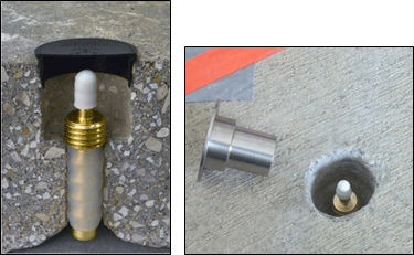
Figure 7-22: Typical Temporary Soil Vapor Probe Typical temporary soil vapor probe, designed to be driven by a direct-push drill rig. The probe tip components (from left to right in the lower left photo) include a disposable drop-off point, probe tip (threaded to attach the tip to a steel drill rod), inert tubing connecting the probe tip to a sampling pump on the surface, and a steel drill rod. A fine mesh screen is located inside the probe tip.
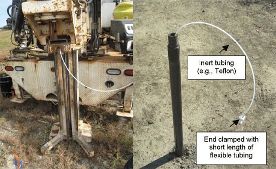
Figure 7-23: Installing a Temporary Soil Vapor Probe Using a Direct-Push Drill Rig After the probe is driven to the desired sampling depth, the steel rod is retracted approximately 1 to 6 inches, allowing the drop-off point to remain at the bottom of the boring, and creating a cavity in the soil that provides access to the soil vapor at the desired depth for sampling. The photograph on the right shows a temporary soil vapor sampling probe in place.
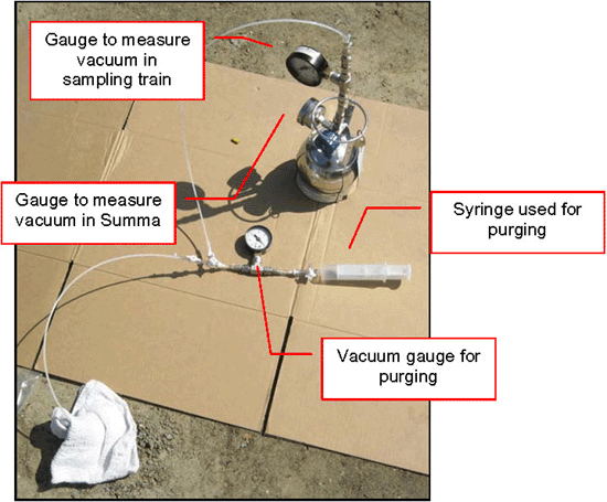
Figure 7-24 Vapor Point Completions Left: Surface completion of flush-mounted well with valve installed. Right: Flush mounted nested well with Swagelok fittings; well in background being purged using an electric pump set at a draw rate of 200 ml/minute.
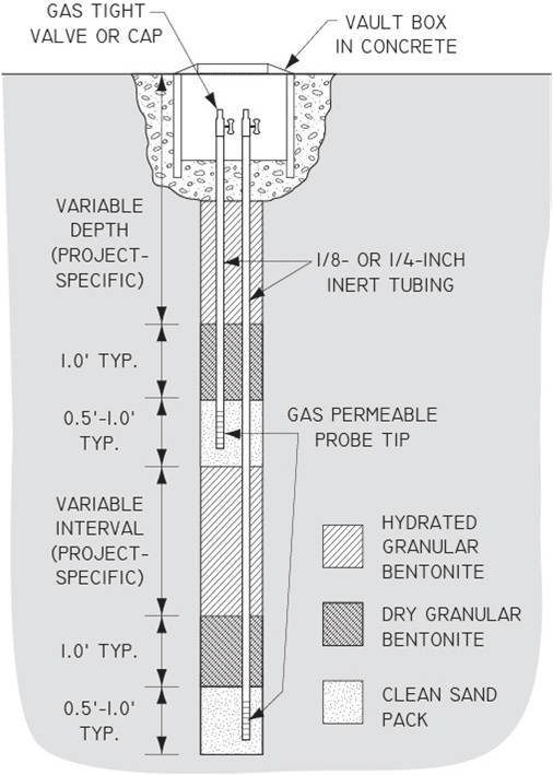
Figure 7-25 Typical Nested Permanent Soil Vapor Sampling Probes
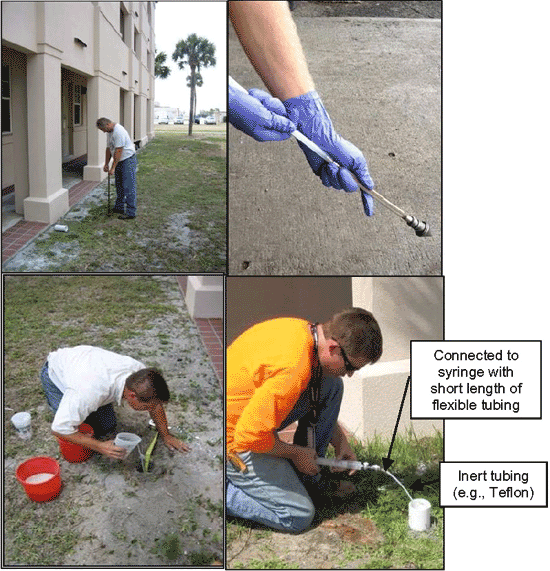
Figure 7-26 Installation of a Permanent Soil Vapor Probe Upper left photo: Hand-augering the borehole. Upper right photo: Preparation of soil vapor sampling point. Bottom left photo: Hydrating the bentonite seal. Tape used to measure depth of borehole, sand pack, and bentonite. Bottom right photo: Purging the completed vapor probe. Surface completion is a 9-inch length of 3-inch diameter Schedule 40 PVC pipe placed into upper 6 inches of the borehole around the probe tubing. A slip cap is placed over the PVC when not purging/sampling.
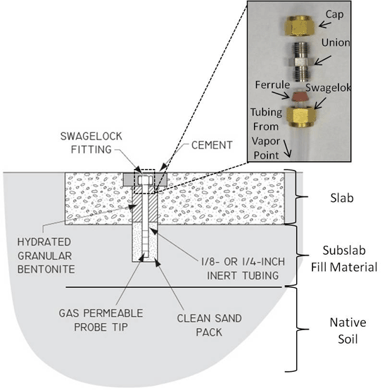
Figure 7-27 Schematic of Typical Sub-Slab Soil Vapor Sampling Probe (see also Figure 7-28 & 7-29).
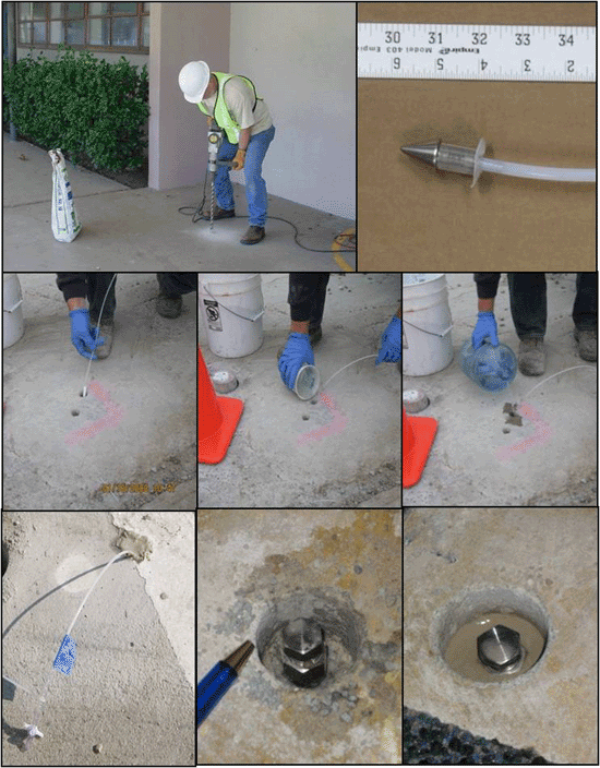
Figure 7-28 Sub-Slab Soil Vapor Sampling Probes Upper left photo: Drilling hole with hand-held rotary hammer drill. Upper right photo: Temporary probe tip. Middle sequence: Inserting probe assembly into hole, pouring granular bentonite, hydrating bentonite seal. Bottom Left: Temporary probe completion. Bottom Middle and Right: Vapor probe with Swagelok termination fitted to hole (note larger diameter hole near surface), final completion with Swagelok fitting on tubing cemented in place (see Figure 7-25).
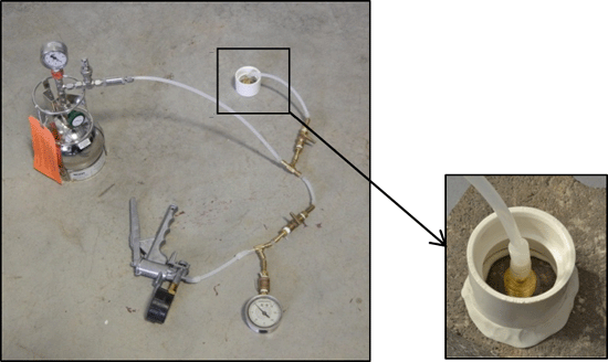
Figure 7-29 Sub-Slab Soil Vapor Sampling Probes Left: Example dual Swagelock setup for connection of vapor point to collection device (see Figure 7-25 and Figure 7-28) Right: Tubing from vapor point and collection device connected with a union joint.
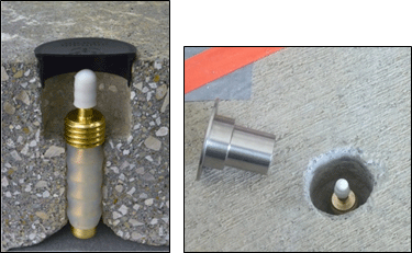
Figure 7-30: Installation of a Vapor Pin™ with a silicon sleeve directly into slab for collection of subslab vapor samples (screw-on protective cap shown in photo to right). Sample collection tubing is connected directly to the top of the probe point (after rubber slip-on cap is removed) and the sample drawn through the base.
The purpose of soil vapor probes is to provide access to subsurface soil vapor so that an active sample can be collected. Soil vapor probes must be properly installed to collect representative soil vapor samples and to minimize the effects of changes in barometric pressure, temperature, or breakthrough of ambient air from the surface. Probes can be either temporary or permanent. The latter typically include a sandpack in the target depth interval of interest and a surface completion that includes a valve and/or a access port for periodic sampling.
7.9.1 TEMPORARY PROBES
Temporary probes typically consist of hollow steel rods driven into the subsurface using manual or direct push drilling methods. The temporary probes are driven to the bottom of the desired sampling interval using expendable or retrievable drive points. Then, the probe rods are withdrawn approximately 1 to 6 inches, leaving the expendable drive point in place and exposing the sampling interval. Narrow tubing with a threaded adaptor at the bottom end is inserted through the steel rods and threaded into the probe tip to form a gas tight seal. The use of tubing with a 1/4-inch to 3/8-inch outside diameter is most common (see Section 7.9.4). An example temporary probe sampling apparatus and typical installation are shown in Figure 7-22 and Figure 7-23.
Sample collection is performed through tubing that is run through the hollow drill rod and connected directly to the sampling probe tip. After collecting shallow samples using rods with retrievable tips, the rods can be advanced to collect deeper samples. The potential for cross contamination should be considered when using the same push rod for the collection of samples at multiple depths.
7.9.2 PERMANENT PROBES
Permanent probes are constructed similar to groundwater monitoring wells installed using auger or direct push drilling techniques. However, permanent probes also can be installed manually within building interiors. Soils should be logged, field screened, and sampled for select contaminants during probe installation using auger or direct push drilling techniques. Documenting soil lithology can be important for development of conceptual site models, including an understanding subsurface vapor transport pathways and mechanisms, and for selecting vapor probe depths.
Permanent probes typically consist of small, inert tubing (e.g. 1/4-inch outside diameter; see Section 7.9.4) extending from the subsurface sampling interval to the ground surface and sealed in place with bentonite to prevent vertical air migration during sample collection. The subsurface end of the tubing is connected to a stainless steel screen or porous stone (airstone) probe tip to prevent particulates from entering the sample probe. Note that polyethylene probe tips are not recommended as VOCs might adsorb to the filter material. The probe tip is typically set halfway between the top and bottom of the sampling interval within a sand pack. Permanent screen implants are typically six inches in length. Placement of a few inches of sand below and above the implant is generally recommended for a total sample-interval sand pack length of approximately one-foot, although deviations can be considered with justification. A sampling interval of greater than one-foot increases the uncertainty in interpretation of measurements since the concentration is averaged over a larger vertical interval ((API 2005). This is especially important for subslab soil vapor samples, where the average concentration of VOCs within one-foot of the slab around preferential pathways into the building should be targeted (see Section 7.6.2.2). Figure 7-24 and Figure 7-25 present several examples of flush-mounted soil vapor points and a schematic diagram of vapor probe point designs.
Approximately 1 foot of dry granular bentonite should be placed on top of the sand pack to prevent infiltration of hydrated bentonite into the sand pack. The borehole is typically sealed to the surface, or to the bottom of the next highest sampling interval, with hydrated bentonite. When installing permanent probes at several depths in the same borehole, the deepest sample interval is always installed first. Figure 7-26 depicts the installation of a permanent vapor probe using a hand auger. Permanent probes should be finished to preclude infiltration of water or the exchange of ambient air in the sample tubing. Surface completions of permanent probes typically include a fitting that allows for soil vapor sample collection and a gas tight valve at the surface when the probe is not in use. Flush mounting or above ground vaults for surface completions are site specific and should be evaluated accordingly. Permanent probes should be purged of three system volumes immediately following installation (see Section 7.10.3) and allowed to equilibrate prior to sampling (see Section 7.10.2).
7.9.3 ADDITIONAL RECOMMENDATIONS FOR SUBSLAB PROBES
Refer to Section 7.8.4 for guidance on the installation of Large Volume Purge (LVP) subslab vapor samples. Temporary, small-volume vapor sample subslab probes are installed in a similar manner as permanent probes. The probe consists of 1/4- to 3/8-inch (outside diameter) inert tubing (see Subsection 7.8.2) with a stainless steel or porous stone probe tip or “implant.” Probe implants should be placed within the first 6 to 12 inches of soil (see Subsection 7.6.2.2). If the probe is to be left in place, the surface termination should be a stainless steel or brass Swagelok compression fitting with a threaded plug to seal the probe. For temporary installations, the probe can be completed with 6 to 12 inches of tubing above the surface with a 2-way valve to seal it. Deeper vapor points can also be set beneath buildings slabs to investigate source-area vapor concentrations (see Section 7.6.2.3). Reviewing as-built plans and screening proposed vapor points using GPR or similar methods to check for rebar and other potential obstacles to drilling is recommended.
As discussed in Section 7.6.2.2, a targeted placement of subslab probes should include: 1) locations of known or suspected, localized subslab sources of contamination; 2) in the absence of the former, the center of the building slab, where concentrations of VOCs from deeper are anticipated to be the highest; 3) between the center of the building and outer, adjacent sources contamination; and 4) in the vicinity of cracks and gaps in the building slab where vapor intrusion is considered to be most likely (see also USEPA 2012d, CalEPA 2011). Examples of the latter include areas where utilities penetrate the building slab, or areas where cracks in the floor could serve as preferential vapor pathways.
Traditional subslab probes are installed by drilling a hole of appropriate diameter through the slab at the targeted location and installing a sample collection point directly into the underlying fill material. Using a rotary hammer drill, a 1¼-inch diameter hole is drilled approximately 1½ inches into the slab to make room for the Swagelok fitting. A 3/4-inch diameter hole is then drilled through the remaining slab thickness and 6 to 12 inches into the underlying sub-slab base material (typically engineered fill).
The inside of the hole should be cleaned out and wiped with a damp towel to remove the drilling dust and ensure an airtight seal. The probe assembly is then inserted into the hole so that the probe tip is just below the slab. The tubing should be cut to the appropriate length so that probe tip is just below the slab and the Swagelok termination is slightly recessed or flush with the slab surface. Clean sand is then poured into the hole until the probe tip is covered to form a filter pack. Granular bentonite is poured to the top of the 3/4-inch hole and hydrated. Care should be taken not to allow water to leak into the filter pack sand.
The Swagelok fitting is then sealed in place with a small amount of quick-drying cement (see Figure 7-27). Either plastic or stainless steel ferrules can be used for Swagelok fittings (plastic shown in photo; steel ferrules include an additional ring washer). To avoid cementing the probe closed, the cement should be poured no higher than flush with the top of the compression fitting. Cement should not be allowed to flow around the threaded plug. Figure 7-28 & Figure 7-29 depict completions for subslab vapor points.
Alternative approaches that can reduce the time, effort and cost of collecting subslab soil vapor samples are being developed. One example includes the “Vapor PinTM,” which is installed directly into the floor slab and does not require the installation of a separate, gas permeable probe tip and tubing into the underlying fill material (Figure 7-30; flush-mount shown). A core is removed from the slab in a similar manner as described above. The side of the boring should be brushed to remove loose material prior to installing a pin in order to obtain a strong seal. A shop vac or similar method should not be used to clean the hole due to the potential to disturb subsurface conditions. If done, then a minimum of 24 hours is recommended to reestablish equilibrium conditions.
The hollow, brass or stainless steel pin is then hammered into the boring (see Figure 7-30). A silicone sleeve around the pin provides a seal against the sides of the hole to prevent leakage of ambient air, eliminating the need for grout. The sampling train tubing is connected to the top of the pin and the sample is drawn directly through the base of the pin. Guidance for installation of the pins and leak tests should be followed if used at sites in Hawaiʻi (Cox-Colvin 2013, b). Similar devices are likely to be developed in the future and can be proposed for use on a site-specific basis. These types of pins have a good record for installation in concrete slabs but difficulty in obtaining an adequate seal has been reported for asphalt. If a slab crumbles during drilling, then silicon putty or similar, non-volatile material may be useful to help seal the annular space around a point.
A small amount of water can be added to holes drilled in slabs (“wet drilling”) if high levels of methane or other potentially explosive gases could be present beneath a slab or other capped area. This can help prevent sparks when the drill bit breaks through the bottom plane of the slab. If used, then an equilibrium time of at least two hours following installation of the vapor point (including vapor pins) is recommended.
7.9.4 SOIL VAPOR PROBE TUBING
Inert, rigid-walled tubing, such as Teflon, nylon (e.g. Nylaflow), or stainless steel should be used as the primary tubing for soil vapor sampling probes (Ouellette 2004, SDC 2011, USEPA 2009). Tests using these materials show minimal (<10%) loss of VOCs during sample collection. Tubing within an outside diameter (OD) of 1/4-inch and 3/16-inch (0.1875) inside diameter (ID) and/or 3/8-inch OD and 1/4-inch (0.25) ID is most commonly used (see Figures 7-25 and 7-26).
Polyethylene and other flexible tubing (e.g., Tygon) as well as and copper tubing adsorb VOCs and should be avoided. Losses up to 80% of VOCS due to absorption has been documented with some types of flexible tubing. A few inches of flexible tubing that can be pinched closed may be needed in addition to the rigid-wall tubing (see Figure 7-23), however, or to connect rigid-wall tubing to sampling equipment (e.g., to syringes; see Figure 7-26). The use of larger diameter tubing to connect smaller rigid tubing introduces a potential for leakage during sampling (see Section 7.10.5),so swageloks should be used instead for connections where possible (e.g., see Figure 7-27). Sampling trains should be tested using a shut-in test prior to collection of samples regardless of the types of connections used.
Storage and handling of tubing is critical. Tubing should be stored in a sealed container to prevent contamination from ambient air or other sources. Avoid leaving tubing near open sources of vapors (e.g., fuel cans, cleaners, etc.) or near auto exhaust..
7.9.5 SOIL VAPOR PROBE ABANDONMENT
When soil vapor probes are no longer needed they should be properly abandoned. Abandonment procedures for temporary probes are the same as for any direct-push borehole (e.g., backfill with hydrated bentonite).
Well vaults should be over-drilled and removed. Several inches of the bentonite seal should be removed and the probe tubing cut as far down as practical. A thin layer (~one-inch) of bentonite should be placed back over the tubing and hydrated to seal it. The well-vault holes should then be filled with concrete and finished flush with the surrounding surface. The concrete used should be of suitable grade for the location. A layer of several inches of sand between the bentonite and the concrete will help prevent heaving of the concrete plug due to wetting/drying cycles of the bentonite. Probes installed in unpaved areas should be abandoned similarly except that clean surrounding soils should be used to fill the holes to grade.
Sub-slab probes should be drilled out, the inside of the hole cleaned with a damp cloth, and the hole filled flush with the slab with lime-based cement, or an epoxy cement or putty otherwise formulated for concrete repair. It is important to carefully clean the hole prior to pouring the cement to ensure a good seal so that the former probe hole does not become a conduit for VOCs to enter the building.
7.10 ACTIVE SOIL VAPOR SAMPLING PROCEDURES
Table 7-6 Sand Pack Porosity Volume (ml)
| Filter Pack Length (inches) | Borehole Diameter (inches) | |||||
| 1.25 | 1.5 | 2.0 | 2.5 | 3.0 | 3.5 | |
| 6 | 36 | 52 | 93 | 145 | 208 | 284 |
| 12 | 72 | 104 | 185 | 290 | 417 | 568 |
| 18 | 109 | 156 | 278 | 434 | 625 | 851 |
| 24 | 145 | 208 | 371 | 579 | 834 | 1,135 |
Note: Assumes sand pack porosity of 30%.
Table 7-7 Tubing Volume (ml)
| Tubing Length (feet) |
Tubing Inner Diameter (inches) | |||
| 1/16 (0.085) |
1/8 (0.125) |
3/16 (0.1875) |
1/4 (0.25) |
|
| 1 | 1 | 2 | 5 | 10 |
| 2 | 2 | 5 | 11 | 19 |
| 3 | 3 | 7 | 16 | 29 |
| 4 | 4 | 10 | 22 | 39 |
| 5 | 6 | 12 | 27 | 48 |
| 10 | 11 | 24 | 54 | 97 |
| 15 | 17 | 36 | 81 | 145 |
| 20 | 22 | 48 | 109 | 193 |
| 25 | 28 | 60 | 136 | 241 |
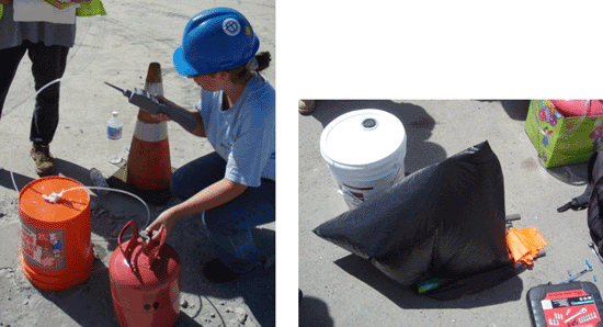
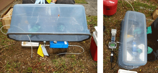
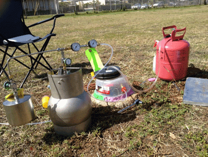
Figure 7-31: Soil Vapor Probe Purging Devices Upper photo: Disposable syringe with 3-way Luer valve (see also Figure 7-26). Middle photo: Pump with flow meter. Lower photo: Large Summa used for purging. Smaller Summa to left used to collect sample after purging; purge Summa closed during sample collection
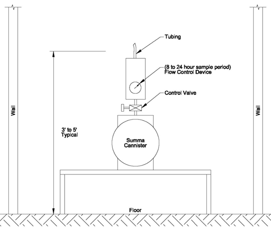
Figure 7-32: Example Vacuum Gauges for Purging and Sample Collection using a Summa Canister Sampling Train (see also Figure 7-34 and Figure 7-35).
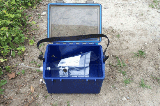
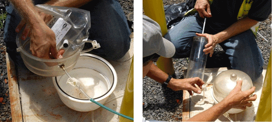
Figure 7-33: Lung Boxes with Tedlar bag. Vacuum is drawn on sealed lung box, causing the Tedlar bag to pull vapor from the collection point and fill.
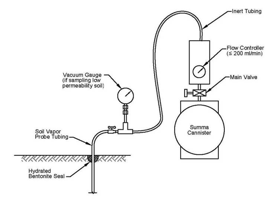
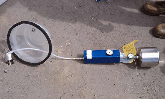
Figure 7-34: Summa canister sampling trains. Upper schematic: Diagram of Summa canister soil vapor sampling apparatus. Lower photo: Teflon tubing connected to flow controller with swage lock and to well point with short length of flexible tubing (allowed well point to be closed for followup sorbent tube sample). Note Tupperware shroud used for leak test. .
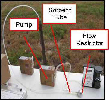

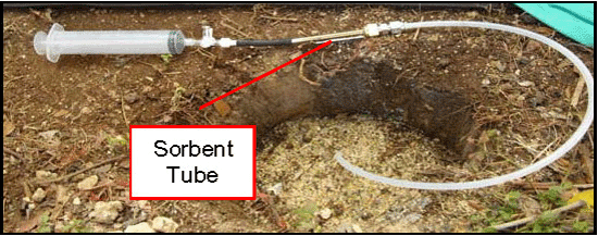
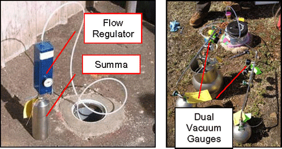
Figure 7-35: Example Soil Vapor Sample Collection Setups Upper photo: Battery powered sampling pump draws soil vapor through the Teflon tubing from the temporary soil vapor probe tip to the sample sorbent tube. A restrictor device reduces the pump flow to the required rate (usually set at laboratory). Note the black and silver air pump calibrator near the restrictor; before sampling, the flow rate is calibrated and recorded for each type of sorbent tube media. Middle schematic and photo: TO-17 sorbent tube soil vapor sampling apparatus. Vapor point tubing connected to sorbent tube inlet with a union and swage lock; pump or syringe connected to outlet of sorbent tube and used to draw sample (latter shown in photo). Lower left photo: Summa canister used to collect soil vapor from a permanent soil vapor point. The blue-bodied flow controller is laboratory-calibrated to restrict sample inflow to a predetermined flow rate. A gauge on the controller’s side indicates vacuum remaining in the canister. Lower right photo: Manifold setup to allow collection of duplicate samples (see also Figure 7-36). Small Summas used to collect samples; large Summa used to purge vapor point. Dual vacuum gauges in each setup used to monitor Summa vacuum and vacuum at well point (flow regulator installed between gauges). Shut-in leak test critical to ensure that sampling train is tight.
Table 7-8 Comparison of Tracer Leak Check Methods
| Method | Advantages | Disadvantages |
| Tracer Method 1 |
|
|
| Tracer Method 2 |
|
|
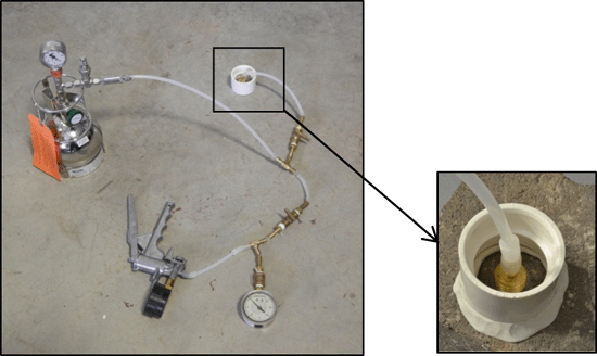
Figure 7-37: Example PVC Coupling “Water Dam” Sealed to Floor with Inert Putty for Leak Testing Slab-mounted Vapor Point. After Cox-Colvin 2013, b. The water level is filled to a level above the tubing connection to the vapor point and monitored during a vacuum test prior to and during sample collection.
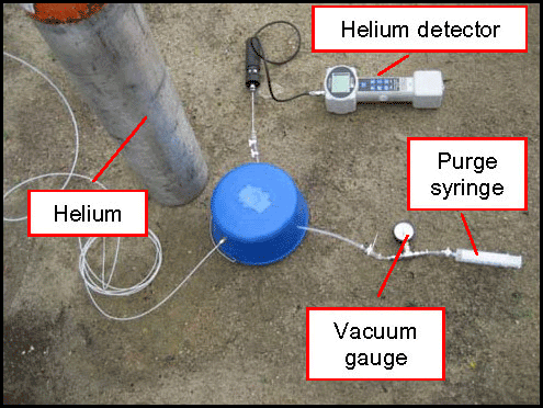
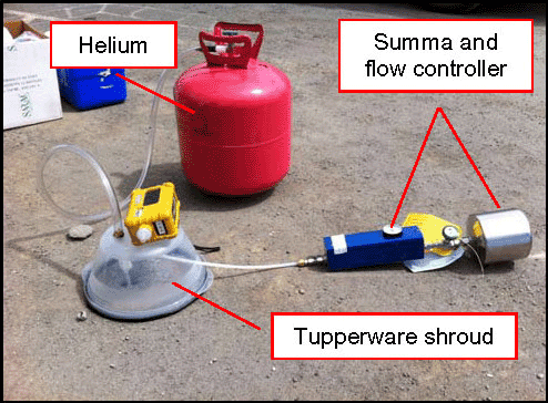
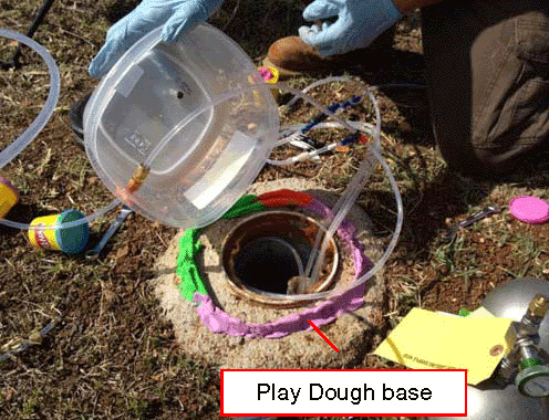
Figure 7-38: Shroud Over Vapor Probe Surface Completion. Upper Photo: System consists of shroud (blue bucket), industrial-grade helium cylinder, field helium detector to measure helium within shroud, and syringe with vacuum gauge for purging. Purged sample tested in field for helium. Sampling train not shown in example. Middle Photo: System consists of Summa and flow controller sampling train, Tupperware shroud (bottom lined with foam door seal), non industrial-grade helium cylinder. Option for use of field helium detector with shroud and field testing of purged sample for helium (not shown in example). Bottom System: Similar to above but Tupperware shroud set into a ring of Play-Doh on concrete base to provide a tighter seal around vapor point. Large Summa used to purge well point; smaller Summa used to collect sample (see also Figure 7-31).
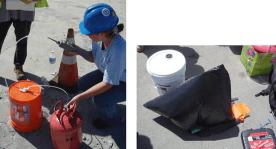
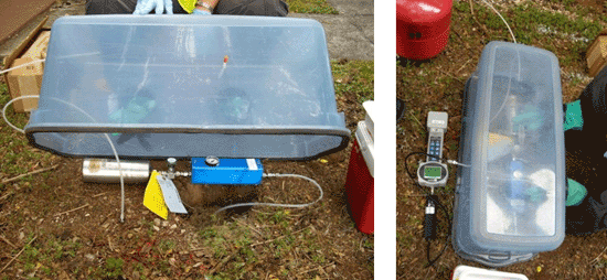
Figure 7-39: Method 2 Helium Shroud Leak Testing Systems Helium released into shroud and used as tracer to identify leaks in both sampling train and vapor probe annular seal. Upper left photo: Five-gallon bucket helium shroud placed over well point and Summa canister-flow controller sampling train (note two ports for injection and monitoring of helium inside shroud). Upper right photo: Use of garbage bag as shroud (helium injected under shroud to fill bag). Lower photos: Large Tupperware container converted to shroud, with fill ports for helium injection and monitoring, plus glove ports to open and close Summa canister for sample collection.
Table 7-9 Comparison of Leak Check Tracers
| Compound | Advantages | Disadvantages |
| Isopropanol |
|
|
| Helium |
|
|
| Difluoroethane |
|
|
The descriptions of active soil vapor sampling procedures in the following sections are general in nature and reflect commonly accepted designs and methods recommended by the USEPA (USEPA 1996c), industry standards (ASTM 2006f) and various other entities (e.g., MDNR 2005, SDC 20111, CalEPA 2012). Alternative designs may be more appropriate depending on sampling objectives
7.10.1 SOIL VAPOR SAMPLE TIMING AND FREQUENCY
Like sample location and depth, the timing and frequency of sample collection will necessarily be a site-specific decision and should be discussed with the overseeing HDOH project manager. General guidance is, however, presented below.
As discussed in Sections 7.2 and 7.5, the objective of the investigation is to develop a CSM that reflects the representative, average subsurface vapor concentrations and vapor intrusion conditions over time and during normal building operation over a period of many years (e.g., assumed exposure durations). Samples collected as part of an investigation should likewise be representative of assumed, long-term, average site conditions.
The collection of soil vapor samples from both the fill material immediately under the building slab and the suspected or known source area is recommended at sites where the distance to the source area is greater than 5 feet (but no closer than 2-3 ft to the water table) and a potentially significant source is present (see Section 7.6.2.3). This will help assess the need to seal cracks and utility gaps in the building floor as an added measure of precaution, in the event that nearby portions of the vapor plume exceed subslab, soil gas action levels even though VOCs meet action levels in subslab samples (see Section 7.14.1).
As discussed in Section 13.2 of the EHE overview, site-specific considerations regarding the timing and frequency of soil vapor sample collection include building HVAC system operation, seasonal weather variations and associated water table fluctuations and tidal effects on groundwater elevation. Multiple sampling events are recommended if the conceptual model identifies the VOC concentrations in source area vapors well above shallow soil gas action levels and the potential for significant, temporal fluctuations in soil vapor concentrations and or the potential for advective flow of vapors into overlying buildings. Recommendations include:
- Collection and comparison of subslab soil vapor samples (or crawl space samples) during periods of the year when air conditioning is and is not routinely used (e.g., summer versus winter months);
- Collection of deep and subslab soil vapor samples (or crawl space samples) during both the wet and dry season for sites where a significant smear zone is known or suspected to be present at the water table and exposure of contaminated soil in the smear zone could vary dramatically over the year.
The collection of seasonal soil vapor samples should be considered at sites where a substantial smear zone that could be exposed during falling water tables is known or suspected to be present. The collection of subslab soil vapor samples during periods of both falling and rising water table may be necessary on a site-specific basis to evaluate the effects of tidal pumping on subslab soil vapor concentrations at high-risk, coastal sites with significant free product on shallow groundwater.
At sites near the coast, the tides can affect groundwater levels, soil vapor samples should be collected at the same point in the tidal cycle in order to obtain data that are comparable from point-to-point and from sampling event to sampling event. The collection of subslab samples during both rising and falling tides (or more specifically water tables) may also be necessarily, especially if significant concentrations of vapor-phase contaminants have been identified in deeper, soil vapor samples.
A single round of soil vapor sample collection will generally be acceptable for sites that meet the following conditions (see HDOH, 2007c): 1) Minimal volume of contaminated, vadose-zone soil is suspected to be present within 30 feet of the building slab (e.g., 10m³, not including capillary fringe zone soils), 2) Less than 30m² area of floating product on water table present, 3) Larger area of floating product present but greater than 30-foot vertical separation distance, and/or 4) Water table fluctuations unlikely to expose a smear zone greater than three feet thick within 30 feet of the building slab. A minimum of one round of samples should be collected at chlorinated solvent sites where groundwater action levels are approached or exceeded or a significant source is present in the vadose zone.
At least two rounds of soil vapor sampling, one during the “dry” season and one during the “wet” season, are recommended prior to negation of potential vapor intrusion hazards for sites that meet the following conditions: 1) Sites with widespread, heavy contamination in vadose-zone soil and/or floating on groundwater within 30 vertical feet or 100 lateral feet of a building slab that do not meet the above-noted conditions or 2) Confirmation of remedial actions at sites where potential vapor intrusion hazards have been documented in the past (e.g., concentrations of VOCs in subslab soil vapor greater than action levels and/or impacts to indoor air above action levels or expected background identified and tied to vapor intrusion).
If more than one round of soil vapor samples are collected, the field procedures (e.g., purge volume), sample containers, and analytical methods should be consistent from one sampling event to the next to allow comparison of the site data over time. The CSM model should be refined to reflect the data collected over multiple sampling events and used to determine the need for additional actions.
Short-term (minutes or days), temporal variation of concentrations in soil vapors due to changes in temperature, barometric pressure, and wind speed due to passing storms are likely to be nominal for uncovered areas at depths of 2 feet bgs or more (USEPA 2007e). Infiltration from rainfall can potentially impact soil vapor concentrations by displacing soil vapor, dissolving volatile organic compounds, and by creating a “cap” above the soil vapor. In practice, infiltration from brief, large storms only penetrates into the soil on the order of inches. Soil vapor samples collected at depths greater than 3 feet bgs are therefore unlikely to be significantly affected. Soil vapor samples collected closer to the surface (less than 3 feet) without surface cover may be affected.
If the wetting front has penetrated to the sampling zone, it typically can be recognized by high vacuums during purging. If high vacuums are encountered when collecting a sample or drops of moisture are evident in the sampling train or sample, a soil vapor sample should not be collected (e.g., vacuum greater than seven inches Hg or 100 inches of water; see Section 7.10.3.2). In addition to potential short circuiting to the surface, imposition of a high vacuum on the soil could cause non vapor-phase VOCs to be stripped in free product, sorbed to soil or dissolved in soil moisture and bias the resulting vapor sample. Measurement of soil moisture can also be useful if shallow sampling is performed during or shortly after significant rainfall (e.g., greater than 1 inch; SDC 2011
7.10.2 SOIL VAPOR PROBE EQUILIBRATION
Subsurface soil vapor conditions are disturbed during installation of soil vapor sampling probes. In general, temporary probes advanced with manual or direct push methods result in the least disturbance to soil vapor conditions and can be purged and sampled relatively soon after installation. Permanent probes result in greater subsurface disturbance and require a longer equilibration time.
Recent studies conducted by the USEPA have evaluated equilibration times for a variety of probe types (USEPA 2010c, USEPA 2010d). Data from these studies indicate that temporary probes (see Section 7.9.1) achieve approximately 80% equilibration within two hours of installation, while permanent probes installed in direct-push boreholes typically require eight to twenty-four hours to fully equilibrate. Probes installed in boreholes advanced with auger methods are expected to require up to 48 hours to equilibrate.
The time between probe installation and sampling will depend on the investigation objectives and the data quality requirements. For example, if a soil vapor survey is conducted using temporary points to map the extent of a vapor plume, and the sample data are not intended for use in risk assessment or site closure decisions, then sampling 30 minutes after installation would be acceptable. To obtain quality data for decision making, permanent soil vapor probes should be allowed to equilibrate for at least 24 (direct push) to 48 (augers) hours before sampling
As a default, the following equilibration times are recommended before proceeding with soil gas sampling (refer also to CalEPA 2012):
- For soil gas wells installed with the direct push method, do not conduct the purge volume test, leak test and soil gas sampling for at least two hours following completion of vapor probe installation;
- For soil gas wells installed with hollow stem or hand auger drilling methods, do not conduct the purge volume test, leak test and soil gas sampling for at least 48 hours following completion of vapor probe installation.
- For subslab soil gas probes installed in soil beneath the slab, do not conduct the purge volume test, leak test and soil gas sampling for at least two hours following completion of vapor probe installation
- For vapor collection pins installed directly into the slab, do not conduct the purge volume test, leak test and soil gas sampling for at least twenty minutes following completion of vapor probe installation (e.g., see Cox-Colvin 2013);
Cap the vapor pins immediately after they are installed in order to minimize the potential for cross slab air movement, including the potential migration of indoor air into the subslab area (e.g., air conditioned buildings under positive pressure).
7.10.3 SOIL VAPOR PROBE PURGING
Vapor probes should be purged of stagnant or ambient air in tubing and other equipment and filled with soil vapor prior to collection of a sample. The volume of air space in sand packs installed with the vapor point should be included in purging if less than 24 hours has lapsed since installation of the probes. The amount of time between purging and sample collection should be minimized.
The system volume is approximated as the sum of the volume of the open borehole interval (for temporary probes) or the sand pack porosity (for permanent probes) and the volume of tubing from the probe tip to the sample collection device.
Tables 7-6 and 7-7 show the sand pack volume (does not include tubing) and tubing volumes, respectively, for common borehole and tubing sizes.
Opinions vary on the optimum volume of vapor to be purged from a vapor point prior to the collection of a sample. Several published studies for relatively coarse soils indicated only minimal differences in VOC concentrations with different purge volumes (refer to SDC 2011). For the purposes of this guidance, it is recommended that temporary probes be purged of one to three system-volumes immediately prior to sampling. Permanent probes should be purged of three system-volumes after installation and then allowed to equilibrate.
Following equilibration, it is only necessary to purge three tubing-volumes prior to sample collection, as the sand pack is assumed to be in equilibrium with the surrounding native soils. The volume purged between different vapor points set at similar depths at a site should be approximately the same.
For in-slab, pin-type vapor points (e.g., Vapor PinsTM), minimal purging is required due to the small volume of air associated with the pin and tubing. Purging and monitoring prior to collection of a sample can be carried out until VOC and other target parameters (e.g., O₂) appear to stabilize (e.g., using a PID). A minimum 30 second purge at a rate of 200ml/minute is recommended as a default.
Attempting to purge tight soils using a PID or similar instrument can induce an undesirably high vacuum on the soil, lead to inaccurate readings and even damage the instrument. Under these circumstances, an alternative is to collect an adequate volume of gas in a separate container to allow for field testing (e.g., use of a lung box and Tedlar bag; see Section 7.10.3.2). For example, a five-minute purge at 200mL/min can be used to fill a one-liter, Tedlar bag, which can then be tested using a multi-gas instrument as well as a landfill gas analyzer and/or helium detector, as needed. This approach also avoids the need to attach an instrument directly to the sample train tubing.
Probe purging can be accomplished using a syringe equipped with a three-way valve or a pump (Figure 7-31, see also Figures 7-24 and 7-26). Large Summa canisters can also be used for purging well points (ASTM 2006f; see Figure 7-31). Syringes are an inexpensive and simple approach for purging small volumes up to one liter. For larger purge volumes, a pump with variable flow rates and a flow meter should be used. The pump flow rate should not exceed 200 ml/minute unless it can be demonstrated that the vacuum imposed on the subsurface soil does not exceed seven inches of mercury. A PID can also be used to purge a well point provided that it does not cause an excess vacuum on the soil. Typical flow rates for PIDs range from 100 to 300 ml/minute.
Over purging a well point can have several drawbacks (SDC 2011). The larger the quantity of soil vapor drawn, the greater the uncertainty in the location of the collected sample. Large purge volumes also create a risk of short circuiting to atmospheric air along the outside of the probe body. Large purge volumes can also create vacuum conditions in the soil that could cause contaminant partitioning from soil or free product into the gas phase or cause a large volume of ambient air to be drawn into the formation after the purging equipment is removed.
7.10.3.1 FLOW RATE
A flow rate of 200 milliliters per minute or less is recommended during purging and sampling (SDC 2011, CalEPA 2012). This is intended to keep the vacuum imposed on the soil to below seven inches Hg (100 inches of water) and avoid migration of otherwise sorbed VOCs into the air-filled pore space (see following section). Lower permeability soils may require lower flow rates in order to control the vacuum. A maximum flow rate of 200 ml/minute also helps to minimize the chance of breakthrough during the collection of sorbent-tube samples. Short circuiting to the atmosphere is of less concern for deep wells (e.g., >15ft bgs). A vacuum of seven inches Hg or less should be maintained during sampling, however, in order to minimize volatilization of sorbed VOCs (see below). Packers or other methods may also be required to isolate targeted depth zones.
Summa canisters should be used with flow controller devices supplied by the laboratory and calibrated to an appropriate flow rate. Flow rates are typically set for the flow controller by the laboratory and cannot be adjusted in the field. For example, a flow rate of 200 ml/minute equates to a five minute draw time for a one-liter canister. When purging a well point or collecting a vapor sample with a syringe, the flow rate is maintained by drawing the plunger back at a steady rate. When purging or collecting with a pump, a flow meter should be used to control and measure the flow rate. The flow rate should be read and recorded periodically (e.g., every five minutes or less).
7.10.3.2 VACUUM CONDITIONS AND TIGHT SOILS
The purging and sample collection vacuum should be less than seven inches Hg (100 inches of water; SDC 2011, CalEPA 2012). Increasing the vacuum on the sampling system (e.g., resulting from low permeability soils, high purge or sample flow rates, or high soil moisture) can result in a biased sample. Imposition of a high vacuum on the soil could cause non vapor-phase VOCs in free product, sorbed to soil or dissolved in soil moisture to be stripped and bias the resulting vapor sample. As flow rates and vacuum levels increase, the risk of leakage in the sampling probes increases. High vacuums for sample points within a few feet of the water table can also cause water to be pulled into the sample container. This not only causes potential problems for the laboratory, but also compromises the integrity of the sample data since vapor-phase compounds could partition into the water during storage and shipment of the sample. If water is drawn into a sample container then the sample should be recollected (preferred) or the resulting sample data should be flagged and qualified in the site investigation report.
The vacuum should be measured and documented during purging and sample collection using a vacuum gauge placed between the probe and sample container (Figure 7-32). Note that the gauge on the flow controller for the Summa canister measures the vacuum in the canister, not the vacuum applied to the soil vapor probe.
A qualitative method to quickly determine if the permeability of the soil could lead to an excessive vacuum is to hook up a 20cc to 50cc gas-tight, plastic syringe to the probe and pull on the plunger (SDC 2011). If the plunger is difficult to pull (compare to pulling outside air) or if the plunger is pulled back towards the probe after released, then there is likely too little permeability to get an uncompromised sample. When sampling in relatively permeable soils (e.g., sands, or silty sands) using a syringe, a vacuum gauge is not typically needed as the sampler can feel the vacuum while drawing gas into the syringe.
If the purging or sampling vacuum exceeds seven inches Hg during sample collection, the sample collection flow rate should be reduced. This might be able to be accomplished by progressively closing the valve to the Summa canister. If this doesn’t work, then an alternative flow controller with a lower flow rate (e.g., <100ml/minute) might be necessary. The potential need for a low-flow controller should be assessed prior to the collection of samples based on the geology of the site and prior sampling experience, if available.
If a continued reduction in the flow rate does not reduce the sampling vacuum, then an alternative vapor point would be installed with a large sand pack emplaced in the zone of interest (SDC 2011). The sand pack should have an interstitial void volume of approximately three liters, which implies the use of approximately ten liters of sand for the pack. A vapor point is installed in the pack and completed at the surface. The top of the sand pack should be at least five feet below surface grade. The pack should be capped with bentonite to prevent break though to ambient air.
A vapor sample should only be collected after the sand pack has reached equilibrium with the surrounding, native soil. This can be expected to take approximately two weeks (SDC 2011). Only one purge volume equating to one tubing volume should be removed. Tubing size should be selected so that the purge volume does not exceed 200 milliliters. Purging 200 milliliters is unlikely to induce a significant vacuum in the probe given the substantially larger void volume in the sand pack. Sample size should be limited to one liter. The vacuum within the vapor probe should be measured during sampling to ensure that seven inches Hg is not exceeded during the purging and sample collection
7.10.4 SOIL VAPOR SAMPLING TRAINS
A variety of sampling systems can be used to collect representative soil vapor samples. Individual laboratories typically provide guidance on recommended designs of sampling trains (e.g., Air Toxics 2012, Air Toxics 2012b). The system should be selected based on the type of sample container, the sampling probe, and the overall sampling objectives. The primary requirements are that the system forms a gas-tight sample train from the probe to the sample container, with a means of controlling the sample flow rate and gauging the vacuum in the system.
Tedlar bags can also be filled using a lung box. A lung box is an air-tight container with ports for the soil vapor probe tubing and separate tubing to a pump. The Tedlar bag is connected to the vapor probe tubing and then placed inside the lung box. A pump is used to evacuate the lung box, which causes the Tedlar bag to expand, drawing in soil vapor (Figure 7-33).
A schematic diagram and photograph of a soil vapor sampling apparatus for collecting samples in Summa canisters is depicted in Figure 7-34 and includes the following major elements: the vapor probe tubing, a vacuum gauge, sample tubing (inert tubing such as Teflon, nylon, or stainless-steel), a flow controller, Summa canister, and gas-tight fittings.
The valves and gas-tight fittings must be closed at all times to prevent ambient air from entering the system except when actively purging or collecting a sample. This is especially critical if the sample collection vacuum is elevated (see Subsection 7.10.3.2).
Figure 7-35 shows several typical sampling apparatus in which soil vapor samples are being collected with a sorbent tube and Summa canisters.
In the bottom, right-hand photo of Figure 7-35, the dual vacuum gauges are used to read the vacuum in the Summa (gauge nearest Summa) and the vacuum imposed on the soil as the sample is being collected (gauge closest to well point). A small, pre-calibrated flow regulator is present between the gauges. The vacuum imposed on the soil will be near zero in highly permeable soils but could exceed 10 inches of mercury in tight, clayey soils. Both of these gauges should remain stable during the initial shut-in test of the sampling train (see Subsection 7.10.5.1).
7.10.5 SOIL VAPOR PROBE LEAK TESTING
Leak tests are an important part of quality assurance and are strongly recommended for each vapor sample. The nature of leaks tests carried out as part of a site investigation should be clearly presented and discussed in the resulting report. Leaks in sampling train fittings or leaks at the vapor point annulus can result in dilution of the soil vapor samples with ambient air and under reporting of actual contaminant concentrations. Most leaks occur in the sampling train, rather than in the annulus around the vapor probe surface seal. Excessive vacuum conditions resulting from low porosity soils or high moisture content soils can exacerbate the potential for ambient air leakage. The use of Teflon tape in Swagelok fittings can also cause leaks and should be avoided.
Three types of leak tests are described: 1) A “shut-in” test to determine the tightness of the sampling train in the field, 2) A “water dam” test for field testing of the integrity of the vapor point when installed into a slab or other relatively impermeable surface and 3) A tracer test to determine the presence or absence of gas introduced around the vapor point and/or the sampling train in the sample that is collected. Performance of a shut-in test of the sampling train is recommended prior to the collection of all soil vapor samples. As described below, this allows the tightness of the sampling train to be quickly evaluated in the field. A water dam test, as described below, or equivalent test is recommended for vapor points installed in intact slabs prior to sample collection. This allows the tightness of the annular space around the vapor point to be quickly tested in the field.
Tracer tests are recommended to test the tightness of vapor points installed in soil, cracked slabs, pavement or other cases where a bentonite seal is used to prevent the infiltration of ambient air during sample collection. Tracer gas leak tests are also recommended for high-risk or high public profile sites where where lab data are desired to confirm sampling chain and vapor point tightness. As described below, two tracer gas methods are recommended: (1) Application of a leak check compound to the vapor probe surface seal or (2) Application a tracer gas to the entire sampling apparatus. Table 7-8 provides a comparison of the two leak check methods using a tracer gas.
Use of one of the two tracer methods described above is recommended for vapor points with connections that cannot be included in a shut-in test and for all samples collected from a depth of 5 feet or shallower, due to the increased risk of a leak in the annular seal. This will help to verify that short circuiting is not occurring at surface connection points and/or that there is an adequate annular seal for shallow samples. As discussed below, field measurement for the presence or absence of the tracer in the initial sample drawn from the well point can be used to help verify the integrity of the vapor point prior to submittal of samples to a laboratory (e.g., collection of an initial sample in a Tedlar bag and testing for helium using a hand-held field meter).
A simple shut-in test will be adequate for the routine collection of soil vapor samples when the depth of the probe is greater than 10 feet and all connections in the sampling train can be included in the test. Testing the tightness of the vapor point connection with the ground surface is less critical in these cases given the depth to the sampling point, although a seal should still be placed around the point. A combination of a field shut-in test with a water dam (for intact slabs) and/or the Method 1 tracer test described above will be adequate for the majority of remaining samples. The use of a full shroud over both the sampling train and vapor point could, however, be recommended or even required for sites with a high public profile, sites involved in legal actions, or sites where the integrity of previously collected samples is in question.
Note that simple release of tracer gas around sampling train connections and the vapor probe seal at the ground surface in the absence of a shroud is not recommended, since the concentration of tracer gas around the test points can be difficult to maintain and lengthy release times may be required to draw an adequate amount of tracer gas into the sample container and identify a significant leak.
Be aware that consultants have reported false positives for some types of helium field detectors due to very high concentrations of C5-C12 hydrocarbons in vapors in soil gas. This can be assessed prior to purging and sample collection by connecting the helium detector directly to the vapor point and evaluating the response. Ultra high-purity helium (e.g., Grade 5) is recommended for leak tests due to potential petroleum and other contaminants in cheaper, “party-grade” helium
High levels of light-end, petroleum vapors have also been reported to cause false, elevated readings of methane in vapor samples using a standard, landfill gas analyzer. The use of a carbon trap is recommended when evaluating methane using field instruments at sites where high levels of petroleum may be present in soil gas (see also Subsection 9.4). A carbon trap will retain VOCs, but not methane, and can allow for a more refined estimation of the level of methane present. If a carbon trap is reused, it is recommended to always have gas flow through a carbon trap in the same direction.
7.10.5.1 SAMPLING TRAIN SHUT-IN TEST
A sampling train shut-in test is recommended prior to the collection of all soil vapor samples. The shut-in test is performed by isolating the sampling train from the vapor sampling point and applying a vacuum to the sampling train. The applied vacuum should hold steady (not decrease) for at least 60 seconds. The start and end vacuum should be recorded and reported.
Figure 7-36 depicts example sampling trains arranged for a shut-in test. The system consists of a gas tight 2-way valve at the vapor probe termination, a 3-way valve to connect the vapor probe to the sample container, and a vacuum gauge and syringe with shut-off valve. The 2-way valve is closed and the sample container valve is closed to seal the sampling train. A vacuum is then applied by drawing back the syringe plunger. The vacuum in the sampling train is then monitored for one to five minutes, with a longer time used for more complex trains that have multiple connections or that otherwise might be especially susceptible to leaks. The sampling train can be considered to be adequate “tight” if the apparent loss in vacuum is less than 0.5 in mercury. The second example in the figure consists of a more simple arrangement, with a clamp and short length of flexible tubing included at the well point and used to seal the sampling train. A vacuum is applied by opening the valve on the Summa canister. The vacuum is monitored using the gauge on the flow controller. If the sampling train does not hold a vacuum, then all connections should be rechecked and the shut-in test repeated.
7.10.5.2 WATER DAM VAPOR POINT TEST
A “water dam” offers a simple and inexpensive method to test for leaks around vapor points installed into a slab or other relatively impermeable surface (e.g., see Cox-Colvin 2013b). For a flush-mount installation, water is poured directly into the depression cut into the floor around the vapor point (see Figure 7-30). For a stick-up installation, a coupling can be sealed to the floor around with non-volatile putty and then filled with water (Figure 7-37).
Pour enough distilled water into the water dam containment or the annular space of a flush-mount depression to immerse the tubing connection to the vapor point. Note that water soluble clays such as Play-Doh might absorb too much water to be suitable for tests that last more than one hour. Assemble the sample train and connect it to the vapor point. Perform a shut-in test to verify that the sample train can hold a vacuum for one to five minutes with no more than 0.5 in Hg loss of vacuum (see previous section). Purge the vapor point and monitor the water level in the dam. The water level might drop slightly due to absorption into the concrete. A sudden drop in water level, the appearance of water in sample tubing or other indication of water entering the sub-slab is most likely indicative of a significant leak, however. If this occurs then remove the distilled water and reposition or reseal the vapor point to address the leak.
7.10.5.3 TRACER METHOD 1 – APPLICATION OF TRACER GAS TO SURFACE COMPLETION POINT ONLY
Under Tracer Method 1, once the shut-in test has been successfully completed, a leak check compound is applied to the surface completion of the probe. In the first example, the leak check compound is applied by wetting a towel with liquid compound (e.g., Isopropanol) and placing it around the probe tubing at the ground surface (see Figure 7-36). Isopropanol is included as a targeted VOC in the lab analysis of the sample. In the second example, a small shroud is placed over the surface completion and the shroud filled with a tracer gas like helium (Figure 7-38). Leaks around the probe seal can be tested in the field by drawing a purge sample with a syringe and testing it for helium, as depicted in the first example. As an alternative or as a second check, helium can be included as a targeted VOC in the lab analysis of the sample (see second example). A concentration of 10-30% helium is typically targeted and maintained in the shroud. Advantages and disadvantages of different tracer compounds are discussed in the following sections.
On uneven surfaces it may be useful to place the shroud in a ring of bentonite clay to obtain a better seal around the base of the shroud and minimize the escape of helium. In the lower photo of Figure 7-38 the consultant used a ring of Play-Doh to seal the base of the shroud. Play-Doh is a non-toxic mixture of flour, water, salt, boric acid and mineral oil. Volatile chemicals associated with the mineral oil are negligible and not expected to interfere with leak detection or samples collected.
7.10.5.4 TRACER METHOD 2 – APPLICATION OF TRACER GAS TO ENTIRE SAMPLING APPARATUS
Figure 7-39 depicts several alternative, shroud configurations for enclosure of the entire sampling apparatus (Method 2), including sample container, all tubing and connections, and the vapor probe surface completion in a shroud, which is filled with tracer gas.
A concentration of 10-30% helium is typically targeted and maintained in the shroud. A hand-held helium detector can be used to monitor helium concentrations within the shroud. Purge tests can be conducted in the field to test for annular seal leaks. In addition, the sample submitted to the laboratory is analyzed for the tracer gas.
Five-gallon buckets modified to include ports for sampling train tubing and helium injection and monitoring are currently the most commonly used for full shrouds. Note that a Summa canister sampling train that includes an older, flow controller may not generally fit under a five-gallon bucket shroud. A smaller, more compact flow controller should be used instead. Garbage bags offer a last, easy-to-find resort, but can be difficult to keep sealed and inflated in the field, especially on a windy day and are not recommended for routine sampling.
An advantage of the full-system shroud is the ability to document the lack of a leak in both the sampling train and the vapor point seal by testing for helium in the sample analyzed by the laboratory. Combination with a field shut-in test of the sampling train as described in the previous section is still strongly recommended. This will allow significant leaks in the sampling train to be identified and addressed at the time of sample collection. If helium is identified in the sample that is subsequently collected and analyzed then it can also be concluded that the leak occurred around the vapor point annular seal. A disadvantage of full-system shrouds is the volume of helium required, as well as the increased time and cost of sample collection in the field. Monitoring the vacuum gauge on the flow controller without opening the shroud and loosing the helium is only possible if a clear container or bag is used. This is one advantage of the large Tupperware shroud.
7.10.5.5 TRACER GAS CONCENTRATION MEASUREMENT
For both methods, the concentration of tracer gas in the shroud should ideally be measured and monitored in the field using a hand-held field meter. A concentration of 10-30% helium is typically targeted and maintained. If the field meter is selective for the tracer gas compound (e.g., a helium detector used with helium tracer), then a pre-sample can be collected and checked in the field for tracer gas prior to collecting the formal sample. The formal sample should be analyzed by the laboratory for the leak check compound.
The amount of leaking, if any, can be quantified by comparing the tracer gas concentration measured in the shroud to the concentration measured in the sample. If the leak is less than ten percent of the original concentration of the tracer gas in the shroud then the sample can be considered acceptable (i.e., sample concentration less than 1% to 3% for original concentration in shroud of 10-30%). This indicates that no more than ten percent of the sample submitted to the lab was ambient air and that reported concentrations of VOCs are within ten percent of the actual concentration of VOCs at the vapor point in the field at the time the sample was collected. If a field meter is not used to monitor the concentration of tracer gas in the field then the results of the leak test can only be qualitatively evaluated and any detection of helium will be flagged as a potentially significant leak. Fully document and discuss any detections of leak check compound in the soil vapor investigation report.
7.10.5.6 SELECTION OF LEAK CHECK COMPOUND
The selection of leak check compounds is site and analysis specific. Considerations include whether it is a known or suspected contaminant at the site or included in the laboratory’s list of target analytes for the method being used, and whether it can be monitored with portable measurement devices. Common leak check compounds are isopropanol (2-propanol or “rubbing alcohol”), helium, and difluoroethane (found in “office duster” cans). Each of the compounds has a variety of advantages and disadvantages.
Isopropanol is readily available, inexpensive, and does not require the use of a shroud, as it can be applied to a towel placed around the vapor probe, although it can also be used with a shroud by placing the towel inside the shroud. Isopropanol is also more dense than air and may be particularly useful for testing leaks associated with the anular space of the vapor point (see Figure 7-43). A further advantage of isopropanol is that it can be detected using methods TO-14, TO-15 or SW8260.
A disadvantage, however, is that selective field meters for isopropanol are not readily available and leaks cannot be readily identified in the field, as can be done with helium. Because it is handled at high concentrations, a relatively small and otherwise minor leak (i.e., <10%) can also significantly interfere with the analysis and require reporting limits for VOCs to be raised above target action levels. Quantification of leaks is likewise difficult, since the original concentration of vapor-phase isopropanol under the shroud can at best be estimated based on its vapor pressure. Isopropanol is also sometimes used as an additive in gasoline. This could again lead to false leaks for sampling at gasoline-release sites.
When using liquid tracer compounds, extreme care also needs to be taken to not contaminate the sampling train parts with tracer compound. Gloves should always be worn when handling the tracer compound. A new pair of gloves should be worn when handling and assembling sampling train components. Ideally, one field technician will be assigned to handle the leak check compound and a second field technician will be assigned to handle and assemble the sampling train.
Helium is commonly used as a leak detection tracer, especially for sampling trains. Helium concentrations can be readily measured in the field using a selective hand-held meter. A further advantage of helium is that its presence in a sample, even at high concentrations, will not interfere with TO-14, TO-15 or SW8260 analysis for VOCs. This allows for a more reliable quantification of leakage. However, the laboratory must run a separate analytical method to analyze for helium. A potential disadvantage of helium is that it is lighter than air. This requires that care be taken to ensure adequate mixing under a shroud if it is used as a tracer for leak detection around vapor points.
Difluoroethane (in office duster cans) is readily available and simpler to handle than helium cylinders and can be analyzed using methods TO-14, TO-15 or SW8260. However, like isopropanol, selective field meters are not readily available.
Table 7-9 provides a comparison of these leak check compounds.
7.10.6 SOIL VAPOR SAMPLE COLLECTION STEPS
The following general steps should be followed when collecting soil vapor samples:
- Allow the sampling probe to equilibrate with the subsurface (see Section 7.10.2).
- Check all valves and fittings for integrity by either performing a vacuum leak test or applying a leak check compound during purging and sample collection (see Section 7.10.5).
- Purge the sampling apparatus as discussed in 7.10.3.
- Collect the soil vapor sample into the appropriate sample container.
- Disassemble the sampling apparatus making sure to close the valves on the sample container and the soil vapor sampling probe.
- Transport the sample to the analytical laboratory under appropriate conditions (based on the analytical method[s] employed) following standard chain-of-custody procedures.
7.10.7 SOIL VAPOR SAMPLE NOTES AND LOGS
Good field notes and logs are important components of soil vapor investigations. Take clear notes in the field. State the goals of each planned activity at the beginning of each day or shift. Document the names of personnel responsible for carrying out different activities, as well as site visitors. Be certain to include units of measurement. Note any nearby activities that could release chemicals to the air (e.g., smoking, recent painting, cleaning with solvents, generators, operation of motor vehicles, passing of cars on roadways, etc.).
Example information that should be included in a sample log includes:
- Sample identification;
- Names of sampling personnel;
- Date and time of sample collection;
- Sampling depth;
- Sampling methods and devices;
- Purging and sampling rates;
- PID readings;
- Soil vapor probe system volumes;
- Volume of soil vapor extracted prior to sampling;
- Sample volume;
- If canisters are used, vacuum of canisters before and after sample collection;
- Apparent moisture content of the sampling zone (e.g., dry, moist, etc.); and
- Chain of custody protocols and records used to track samples from the sampling points to the laboratory
Use field forms to help remind workers of the information that needs to be recorded. Complete every part of the form provided, even if the response is “N/A.” Record data on field logs/forms and sample container tags at the same time. Take photographs during the field work, including broad overviews of the work site and close ups of specific activities. Use a checklist to verify that all equipment has been staged and accounted for prior to initiation of sample collection. Calibrate the field meters and record the method and results in the field notes and on any applicable field forms.
The above represents a necessarily brief overview of requirements for proper documentation of field work. Training by experienced experts and preparation of a detailed work plan can help minimize unanticipated problems during field activities.
7.11 ACTIVE INDOOR AIR SAMPLE COLLECTION PROCEDURES
This section provides a general overview of recommended indoor and outdoor air sample collection procedures and is not intended to be comprehensive. More detailed guidance, including the references noted, should be reviewed prior to the preparation of an indoor air sampling work plan (see HDOH, 2016). Example guidance includes:
- Massachusetts: Indoor Air Sampling And Evaluation Guide (MADEP 2002b);
- DoD: Tri-Services Handbook for the Assessment of the Vapor Intrusion Pathway (DoD 2008);
- Massachusetts: Vapor Intrusion Guidance (MADEP 2010); and
- California: Guidance for the Evaluation and Mitigation of Subsurface Vapor Intrusion to Indoor Air (CalEPA 2011).
Due to potential complications from indoor and outdoor sources of VOCs, the collection of indoor air samples as part of a vapor intrusion study will rarely be practical or recommended (see Sections 7.2 and 7.3). The collection of indoor air samples is only recommended if concentrations in subslab soil vapor exceed 1,000 times (residential) to 2,000-times (commercial/industrial) anticipated background in indoor air, due to potential indoor sources of the same VOCs (see Section 7.7). When needed, however, active sampling of indoor air can be carried out in order to assess the risk posed by contaminants present within a building. Multiple lines of evidence in addition to indoor air data will be required to demonstrate a link between apparent impacts to indoor air and the intrusion of subsurface vapors (refer to Section 7.1 and HEER Office EHE guidance, HDOH, 2016). This includes the magnitude and nature of subsurface contamination (e.g., free product on shallow groundwater), concentrations of targeted VOCs in source area and subslab soil vapor samples, presence or absence of apparent pathways for vapor intrusion, building ventilation design and operation (e.g., likelihood to be over- or under-pressured) and the anticipated concentrations of targeted VOCs in indoor air due to known or suspected indoor and/or outdoor sources.
Discrete sampling approaches are still relied on for the collection of air samples, with six-liter Summa canisters or sorbent tubes most commonly used (see Subsection 7.8 and following sections). Alternative sampling approaches that provide better coverage of targeted, indoor areas and volume of air (i.e., “Decision Units (DU)”) are currently being reviewed (see TGM Sections 2 and 3). Although guidance has not yet been fully developed, this could include the placement of multiple, passive samplers in individual, targeted areas of a building (i.e., “DUs”) and combination of the samplers from individual areas for testing as a single sample. This could allow an improved coverage and resolution VOCs in indoor air, especially in areas of poor circulation or where distinct layering of VOCs in air might be possible (e.g., higher concentration of HVOCs near the floor).
Indoor air samples are typically collected under operational conditions representative of the use of the structure (i.e., doors open or closed depending on their typical condition and the type and operating status of the air conditioning/ventilating system in use in the building). From a risk perspective the objective is to determine the average, long-term concentration of targeted VOCs in the space or spaces occupied by an individual within the structure. As discussed in the following sections, samples collected from multiple locations within a building during different times of the year are usually required to establish a baseline health risk. Although not necessarily representative of long-term exposure conditions or risk, it may be also useful to collect a sample(s) directly from a point of suspected vapor entry, including bathrooms, utility rooms or other areas where utilities protrude through the building floor. As discussed in Sections 7.2 and 7.3, temporal changes due to differences in ventilation and other factors that could influence indoor concentrations of VOCs throughout the year should be evaluated and taken into consideration. For example, buildings may be more prone to vapor intrusion during periods of the year when air conditioning is not routinely used and the potential for the building to be under-pressured due to wind effects is increased. Buildings could also be more susceptible to vapor intrusion during dry periods of the year due to the exposure of subsurface smear zones as the water table falls.
If collecting a combination of indoor air samples, outdoor air samples, and sub-slab soil vapor samples for one project, the indoor and outdoor air samples should be collected concurrently, immediately followed by collection of the sub-slab soil vapor samples. The collection of sub-slab samples simultaneously with the indoor air samples it not recommended because the installation and purging of the probes could introduce site VOCs into the indoor air.
Concurrent outdoor, ambient air samples should be collected when conducting indoor air sampling as part of a vapor intrusion study. Ambient air samples are important for evaluation of potential outdoor sources of targeted VOCs. Like indoor air, ambient air can contain a number of VOCs typically targeted for vapor intrusion studies. Examples include TPH, BTEX and other petroleum-related chemicals associated with auto exhaust as well as chlorinated solvents from nearby industrial activities. Concentrations of these VOCs in heavily populated or industrialized urban areas often exceed purely risk-based, indoor air action levels (HDOH 2016, USEPA 2011e, USEPA 2012, USEPA 2012b).
For residential structures, outdoor air samples should be ideally collected from a representative upwind location, away from wind obstructions such as trees and buildings. The intake should be at five feet off the ground and five to 15 feet away from the building. For commercial structures, outdoor air samples should be collected in representative locations for the intakes of the building HVAC systems.
Outdoor background samples should be collected at locations to minimize bias toward obvious sources of volatile chemicals (e.g., automobiles, lawn mowers, oil storage tanks, gasoline stations, industrial facilities). Outdoor air samples should be collected and analyzed by the same method as indoor air samples and generally for the same time periods as the indoor air samples.
7.11.1 INITIAL BUILDING SURVEY
The indoor environment in any building is a result of the interaction between the site, climate, building heating, ventilation and air conditioning (HVAC) systems, construction design, indoor VOC sources (building materials and furnishings, cleaning fluids, carpet glues, activities within the building, and outdoor sources) and building occupants (smoking, dry cleaning, etc.). An initial building survey is therefore an important part of the indoor air sampling event. This should include interviews with building occupants to assess exposure areas and duration, an evaluation of the building ventilation system and typical operating conditions, an inspection of the building to identify appropriate sampling locations, and an inventory of products or wastes in the building that could release VOCs into the indoor air (i.e., indoor sources). It is recommended that a checklist be used as a guide when conducting building surveys. Vapor intrusion assessment guidance manuals from the USEPA (USEPA 2004e), the Interstate Technology and Regulatory Council (ITRC 2007) and the California EPA (CalEPA 2011) contain example building survey checklists, as do several other state guidance documents (see also vapor intrusion discussion in HEER EHE guidance; HDOH, 2016).
As part of the building survey, potential preferential vapor intrusion pathways should also be evaluated. Utility corridors can act as contaminant migration pathways allowing VOCs to travel long distances. Primary entry points for subsurface vapors include bathrooms, kitchens and utility rooms where water, sewer, gas, electric and telecommunication lines penetrate the floor. Wall outlets for electrical fixtures can also serve as a vapor intrusion pathway.
Depending on the COPC, screening for VOCs using direct reading instruments, such as a high sensitivity PID (e.g. ppbRAE), field portable GC/MS (e.g. Hapsite by Inficon), or combustible gas meter (sometimes known as an explosivity meter) can be useful. These instruments have detection limits in the parts per billion (ppb) range, and are best used for screening at points of potential vapor entry, locating indoor VOC sources, or identifying acute exposure or potentially explosive situations. Note that petroleum vapors are dominated by aliphatic compounds. PIDs primarily target aromatic compounds and are not good indicators of total TPH levels in soil vapors without inclusion of a correction factor (ASTM 2006f; refer also to HDOH, 2012). This is especially important to remember for aromatic-poor vapors from diesel fuel of other middle distillate fuels.
7.11.2 INDOOR AIR SAMPLE LOCATIONS
The concentrations of contaminants in various locations within a building can vary substantially. Indoor air samples should be collected in a manner which represents this variability (see Section 7.7). The number of indoor air samples collected is dependent upon the size, layout, and use of the building. A typical single family residential dwelling (approximately 1,500 ft2) should have at least one indoor air sample collected from each floor and one from the basement or crawl space (if present). Initial samples should target rooms where utilities penetrate the floor or large cracks are obvious, including basements, bathrooms, kitchens, laundry rooms and utility rooms. Although these rooms are unlikely to be continuously occupied, they represent high-risk areas for initial screening of potential problems. Follow-up samples could include bedrooms and living rooms where occupants spend the majority of time in order to provide a better estimate of potential health risk. Larger dwellings in particular may require multiple samples per floor to adequately represent the targeted room or area, especially in areas of poor air circulation. Multi-family residential units and commercial or retail buildings will require a more careful review of the building features and typically warrant multiple sample locations. The sampling plan should take into account the different exposure scenarios (e.g., day care, medical facilities) that exist within the building and any sensitive populations that may be exposed to the contaminated vapors. In structures with basements, both the occupied living areas and basement areas should be sampled from a risk management perspective. Note that ambient concentrations of VOCs from indoor sources will typically be much higher in poorly ventilated rooms such basements and utility closets. For multi-storied residential buildings, consideration should be given to the collection of individual samples or sets of samples on each floor.
Samples are typically collected in the breathing zone of the primary living or working area, approximately three to five feet from the floor (Figure 7-40). If convenient, samples should be collected from the center of the room. The canister or sorbent tube inlet should be placed so that the airflow is unrestricted and the sampling location allows free airflow that is typical of normal conditions. At a minimum, the inlet should have at least one to two meters of free space in an arc of at least 270 degrees around the inlet.
7.11.3 INDOOR AIR SAMPLE DURATION
The duration of indoor air sampling is typically matched to the type of building (see ITRC 2007, CalEPA 2011). In general, sampling duration is typically 24 hours for residential building samples and eight to ten hours for commercial/industrial building samples. Longer duration samples may be appropriate if significant variability in VOC concentrations is suspected. Summa canister flow controllers calibrated to seven-day collection periods are also available. Sorbent tubes can be used for longer duration or larger volume samples.
7.11.4 INDOOR AIR SAMPLE FREQUENCY
Sampling frequency is determined by the CSM, objectives of the study and the nature of the contaminants and should be discussed with the HEER Office on a site-specific basis (see ITRC 2007, CalEPA 2011). A single sampling event is unlikely to yield data that are representative of exposure concentrations over a chronic period of time (i.e., many years). If the contaminant source is non-constant, more frequent sampling should be considered in comparison to constant contaminant sources.
7.11.5 INDOOR AIR SAMPLE CONTAINERS AND ANALYTICAL METHODS
The most common methods for collecting indoor air samples are:
- Use of Summa canisters equipped with a calibrated flow controller for VOCs (Section 7.8.1).
- Use of sorbent tubes connected to a calibrated flow pump for VOCs and SVOCs (Section 7.8.2).
Currently available flow controllers and flow pumps enable collection periods ranging from less than 1 hour to 7 days.
Samples collected in Summa canisters should be analyzed for VOCs in the laboratory using USEPA method TO-14 or TO-15 (Section 7.13.1). Methods TO-14 and TO-15 are similar. Method TO-15 offers additional target analytes over TO-14, however, and has largely replaced the latter. Both methods use gas chromatography-mass spectrometry (GC/MS) instruments and can be operated in full-scan or SIM mode. Full scan mode offers a broader range of target analytes and is typically less costly than SIM mode, but has higher detection levels. SIM mode provides extremely low detection levels. Consultation with the analytical laboratory can assist in determining the most appropriate analytical method for a given air sample. Samples collected on sorbent tubes or passive samplers are typically analyzed using USEPA methods TO-1, TO-2, or TO-17, with the latter most commonly selected (see Subsection 7.13).
For vapor intrusion studies, the suite of VOCs targeted for Indoor and outdoor air samples should be identical to the suite targeted for soil vapor and identified in subslab soil vapor samples. Inclusion of additional VOCs can complicate the evaluation of impacts associated purely with vapor intrusion.
7.11.6 INDOOR-OUTDOOR AIR SAMPLE LOGS
A sample log should be maintained during indoor and outdoor air sampling. Information to be recorded can include:
- Sample identification;
- Names of sampling personnel;
- Date and time of sample collection;
- Weather conditions;
- Building conditions (e.g., HVAC on/off, windows/doors opened or closed);
- Sampling location;
- Sampling height;
- Sampling methods and devices;
- Depending upon the method used, volume of air sampled;
- If canisters are used, vacuum of canisters before and after sample collection;
- Chain of custody protocols and records used to track samples from the sampling points to the laboratory.
General information for field notes and logs presented in Subsection 7.10.7 are also applicable for indoor and outdoor air sampling.
7.12 PASSIVE SOIL VAPOR AND INDOOR AIR SAMPLE COLLECTION PROCEDURES
Figure 7-41: Installing a Passive Soil Vapor Sample Collector by Hand The hole is drilled using a roto-hammer. The soil vapor sample collector is installed using an insertion rod. The hole is then covered.
Passive sampling can be applied to either soil vapor or indoor air. Although the principle is the same in application to these media, the techniques for adsorbent placement, retrieval and analysis are different.
7.12.1 PASSIVE SAMPLING OF SOIL VAPOR
Implementing a passive soil vapor sampling strategy in the field requires careful consideration of the pertinent sampling variables, as described below.
Sample Spacing: The selection of sampling locations for passive sampling is based upon the same considerations as active soil vapor methods: project objectives and the need for adequate coverage. Predetermined and widely spaced grid patterns are most commonly used for reconnaissance work, while closely spaced, irregularly situated locations are commonly used for covering specific source areas.
Collection Depth: Although passive sample collectors have often been installed close to the surface (6 inches to 3 feet), that burial depth has been for convenience in deploying and retrieving the collector and not for technical reasons. In general, passive sample collectors should be deployed as near to the suspected soil or groundwater source as possible in order to reduce the chance of placing the sampler in a pocket of vapor-free soil in an otherwise contaminated area. In addition, collectors buried close to the surface will be very susceptible to air infiltration due to changes in barometric pressure and surface temperature. Therefore, at locations with uncovered soil, it is advisable to bury the collector to a depth of at least three feet. Placement of samplers at shallower depths may be acceptable for paved areas, depending on the objectives of the investigation. Check with the vendor for additional guidance.
Exposure Period: As with collection depth, the exposure period for passive collectors has often been generally selected more for convenience factors than for technical reasons. Typical exposure times have been a few days to a month.
In practice, the exposure period for a passive collector should depend upon the concentration of the contaminant of interest and desired detection levels. In areas of suspected high concentration, collectors can be left in the ground for shorter periods (1 to 5 days). In areas of suspected low concentrations, collectors are often left in the ground for two or more weeks. For areas of unknown concentration, the optimum approach is to determine the deployment time by burying a number of collectors in the same location and measuring them over a period of time.
The key assumption that is made when interpreting passive soil vapor data is that each collector is exposed to the same quantity of soil vapor. Therefore, it is most important that passive collectors within a sampling program be deployed for the same period of time in order for the data to be comparable.
QA/QC: The most important factors affecting the quality of passive soil vapor data is consistency of deployment and potential contamination of the samplers. Sampling teams should be trained in the deployment of the passive sample collectors to ensure consistent methodology is employed for each sample collector that is installed. To assess field contamination, analysis of field blanks and/or trip blanks is extremely important to verify that detected contamination was not from another source, such as the passive collector itself, or from handling and storage during transport to the laboratory.
There are several vendors of passive soil vapor sample collectors and those vendors should be consulted regarding specific installation procedures for their sample collectors and for any adsorbent-specific information, such as uptake rates. A time-sequence series of photographs that illustrates the installation of one vendor-supplied sample collector is shown in Figure 7-41. An example plume map from a grid-based passive soil vapor survey is shown in Figure 7-42.
7.12.2 PASSIVE SAMPLING OF INDOOR AIR
Passive sampling of indoor air is an evolving technique for evaluating potential indoor air impacts. VOCs are the most common target compounds but the technique is applicable to SVOCs as well. The primary advantage in comparison to active sampling is that passive sampling can be done over longer time periods and thereby reflect a longer-term average concentration. It may also be possible to deploy multiple passive samplers within a targeted floor or room and then combine them for extraction and analysis. This helps provide better coverage of targeted areas without increasing lab costs.
There are several vendors of passive indoor air sample collectors and those vendors should be consulted regarding specific applications and instructions for use. Data from passive samplers can be used to help focus the collection of whole air samples or sorbent tube samples.
7.13 SOIL VAPOR AND INDOOR AIR SAMPLE ANALYSIS
The analytical methods selected for analyzing soil vapor or indoor air samples depend on a number of factors. These include the targeted VOCs, desired detection and reporting limits and the manner in which the sample is collected. In Hawaiʻi, soil vapor or indoor air samples are in most cases forwarded to a fixed analytical laboratory on the mainland for analysis. Analytical methods should be consistent within each sampling event as well as for different sampling events to assist in the interpretation of the data.
7.13.1 AVAILABLE ANALYTICAL METHODS
7.13.1.1 VOLATILE ORGANIC COMPOUNDS (VOCS)
A variety of analytical methods are available to measure soil vapor samples all of which give accurate results. Table 7-10 gives a summary of the available methods. Table 7-11 summarizes the methods most commonly used on Hawaiʻi sites. Method versions denoted in the table by Roman letters (e.g., “A”, “B”, “C,” etc.) are for example only and may not include recent updates to the method. Discussion of the most appropriate analytical methods to meet the objectives of an investigation with the laboratory is strongly recommended. Less expensive methods such as TO-3, 8015 and 8021 for VOCs are, for example, primarily used for screening or monitoring purposes. Method 8015 is a comprehensive method for TPH whereas Methods 8260, TO-15 and TO-17 measure individual VOCs by mass spectrometry. Both methods work well for TPH as comprehensive data but GC/MS methods are recommended for final, decision making.
As discussed in the following section, Total Petroleum Hydrocarbons (TPH) should be reported as the sum of C5 to C12 (Summa canister samples) and/or C5-C18 (sorbent tube samples) for vapors associated with all types of petroleum fuels, including diesel and other middle distillate fuels. Unlike soil or groundwater, reporting of TPH compounds as “gasoline-range” or “diesel-range” is not applicable to soil vapors. As discussed in Section 7.13.1.2, vapors associated with diesel and other middle distillate fuels could, in theory, include a large component of C12 and higher aliphatic and to a lesser degree aromatic compounds (see HDOH, 2012). Inclusion of heavier, vapor-phase compounds in the measurement of TPH will require the use of a sorbent method (e.g., TO-17). Recovery of aromatic compounds above C10 and aliphatic compounds above C12 is not currently practical for samples collected in a Summa canister (see Subsection 7.8.1). If a minimum one-liter sample cannot be drawn using a sorbent tube, for example due to potential saturation of the adsorbent material, then a concurrent Summa sample should be collected and used to report light-end VOCs and TPH (see Section 7.8.2). This will almost always be the case for soil vapors associated with petroleum. If initial sorbent data (or prior knowledge at a similar site) indicates that vapors are dominated (e.g., >90%) by C5-C12 compounds then subsequent TPH data can be obtained using Summa samples.
Other analytical methods not listed in Table 7-10 can be utilized on a site-specific basis. A description of the alternate analytical method, rationale for its selection, and analytical results should be fully documented in the final soil vapor or indoor air investigation report.
Table 7-10 Summary of Soil Vapor & Indoor Air Analytical Methods1
| Method No. | Type of Compounds | Collection Device | Methodology | Detection Limit 2 | Reference |
| TO-1 3 | VOC | Tenax® solid sorbent | GC/MS or GC/FID |
0.02 – 200 µg/m³ (0.01-100 ppbv) |
USEPA 1999b |
| TO-2 3 | VOC | Molecular sieve sorbent | GC/MS | 0.2 – 400 µg/m³ (0.1-200 ppbv) |
USEPA 1999b |
| TO-3 | VOC | Cryotrap | GC/FID | 0.2 – 400 µg/m³ (0.1-200 ppbv) |
USEPA 1999b |
| TO-4A | Pesticides/ PCBs |
Polyurethane foam | GC/MD | 0.5 – 2 µg/sample | USEPA 1999b |
| TO-10A | Pesticides/ PCBs |
Polyurethane foam | GC/MD | 0.5 – 2 µg/sample | USEPA 1999b |
| TO-12 | NMOC | Canister or on-line | FID | 200 – 400,000 µg/m³ (100-200,000 ppbv) |
USEPA 1999b |
| TO-13A 3 | PAH, TPH | Polyurethane foam | GC/MS | 0.5-500 µg/m³ (0.6 – 600 ppbv) |
USEPA 1999b |
| TO-14A | VOC (nonpolar) | Specially-treated canister | GC/MS | 0.4 – 20 µg/m³ (0.2-2.5 ppbv) |
USEPA 1999b |
| TO-15 4 | VOC | Specially-treated canister | GC/MS | 0.4 – 20 µg/m³ (0.2-2.5 ppbv) |
USEPA 1999b |
| TO-15A | VOC | Specially-treated canister | GC/MS | 0.005 µg/m³-0.02 µg/m³ (0.002-0 .04 ppbv) |
USEPA 1999b |
| TO-17 3,4 | VOC | Single/multi-bed adsorbent | GC/MS, FID | 0.4 – 20 µg/m³ (0.2-2.5 ppbv) |
USEPA 1999b |
| Method 3C | N₂, O₂, CO₂, CH₄ | Canister | GC/TCD | 20,000 – 150,000 µg/m³ (10,000 ppbv) |
USEPA 1999b |
| Method 16 | H₂S | Tedlar® Bag, Canister | GC/FPD | 100 – 700 µg/m³ (50 ppbv) |
USEPA 1999b |
| 8015B/ 8015D |
TPH/VOC | Tedlar® Bag, Canister, Glass vials | GC/FID | 300 – 3000 µg/m³ (100 – 10,000 ppbv) |
USEPA 1998b |
| 8021B | VOC | Tedlar® Bag, Canister, Glass vials | GC/PID | 4.0 – 60.0 µg/m³ (0.3 – 30 ppbv) |
USEPA 1998b |
| 8260B | VOC | Tedlar® Bag, Canister, Glass vials | GC/MS | 10.0 – 50.0 µg/m³ (0.6 – 25 ppbv) |
USEPA 1998b |
| 8270C | SVOC | Tedlar® Bag, Canister, Glass vials | GC/MS | 1,000 µg/m³ (20,000 – 100,000 ppbv) |
USEPA 1998b |
| D1945-03(2010) | natural gases and mixtures | Tedlar® Bag, Canister, Glass vials | GC/TCD | 800 – 29,000 µg/m³ (10,000 ppbv) |
ASTM 2010b |
| D1946-90(2011) | H₂, O₂, CO₂, CO, CH₄, C₂H₆, C₂H₄ | Tedlar® Bag, Canister, Glass vials | GC/TCD | 800 – 18,000 µg/m³ (10,000 ppbv) |
ASTM 2011 |
Notes (Table adapted from API 2005):
- This is not an exhaustive list. Some methods may be more applicable in certain instances. Other updated, proprietary or unpublished methods may also apply. Passive samplers can also be used for collection and qualitative assessment of some compounds.
- Detection limits are compound specific and can depend upon the sample collection and the nature of the sample. Detection limits shown are for the range of compounds reported by the analytical methods.
- Trapping-type sampling method used to achieve high sensitivity. TO-17 is a one-time thermal desorption method; TO-13 is an extraction method that can be reanalyzed as needed. TO-13 can be used to quantify heavier TPH in vapors but may not adequately capture light-end VOCs (consult the laboratory).
- TO-15 or TO-17 recommended for final, decision making purposes.
| GC – gas chromatography | FPD – flame photometric detector | |
| MD – multi-detector | FID – flame ionization detector | |
| MS – mass spectrometry | SVOC – semivolatile organic compounds | |
| NMOC – non-methane organic compounds | VOC – volatile organic compounds | |
| PAH – polycyclic aromatic hydrocarbons | TCD – thermal conductivity detector |
Table 7-11 HDOH-Recommended Laboratory Analytical Methods for Soil Vapor or Indoor Air Contaminants and Leak Detection Compounds
| .Analyte | Analytical Method | Reference |
| TPH | TO-3, TO-14, TO-15, TO-17, 8015 |
USEPA 1999b USEPA 1998b |
| BTEX, MTBE, naphthalene | TO-15, TO-17, 8012, 8260 | USEPA 1999b USEPA 1998b |
| VOCs (including difluoroethane and isopropanol alcohol) | TO-14, TO-15, TO-1, TO-2, TO-17, 8260, 8021 |
USEPA 1999b USEPA 1998b |
| SVOCs (including PAHs) | TO-17, 8270 (sorbent methods) | USEPA 1998b |
| Oxygen, CO₂, Nitrogen, Methane, Helium | ASTM D-1946, 3C | USEPA 1996j |
| Polynuclear aromatic hydrocarbons (PAHs) | TO-13 | USEPA 1999b |
- According to discussions between HDOH and laboratory staff, The best laboratory method to test for TPH in soil vapors appears to be a combination of both TO-15 (Summa canister samples) and TO-17 (sorbent tube samples) (HDOH, 2012c). A sum of the individual carbon ranges can be more accurately determined from both methods. TO-3 can be far less sensitive than TO-15 and TO-17.
7.13.1.2 TOTAL VOLATILE PETROLEUM HYDROCARBONS
As discussed in Section 9 and the HEER Office EHE guidance (HDOH, 2016 and updates), testing of vapors associated with petroleum should include a short list of target indicator compounds (e.g., BTEX, naphthalene and methane) and Total Petroleum Hydrocarbons (TPH), also referred to as Total Volatile Petroleum Hydrocarbons (TVPH). The target indicator compounds recommended for analysis at petroleum contaminated sites are listed in Section 9, Table 9-5.
Total Petroleum Hydrocarbons represents the sum of the vapor-phase, aliphatic and non-targeted, individual aromatic compounds. This is sometimes subdivided into a “gasoline-range (“TPHg)” category characterized by a dominance of light-end, C5–C12 compounds and a “diesel-range (TPHd”) category characterized by heavier-end, C10–C26 compounds. This is appropriate for testing of soil and water samples, based on the known or assumed type of fuel released.
A distinction between TPHg and TPHd compounds is misleading for vapor-phase petroleum, however, since vapors from diesel and other middle distillate fuels or fuels that include middle distillates (e.g., JP-4, a mixture of gasoline and kerosene, and JP-8, similar to diesel fuel) can contain a significant proportion of lighter end compounds, especially C5-C8 aliphatics. Requesting the lab to report vapor-phase TPH as the equivalent of “TPHd” (i.e., sum of C10+ compounds) could significantly underestimate the actual concentration of TPH in soil vapors.
This issue was investigated and discussed in the HEER Office study Field Investigation of the Chemistry and Toxicity of TPH in Petroleum Vapors: Implications for Potential Vapor Intrusion Hazards (HDOH, 2012, 2012c; Brewer et al 2013). The study suggested that the proportion of C5-C8 aliphatic compounds in vapors associated with middle distillate fuels is highly variable but can be up to 50% or more of the total TPH. Excluding these vapors from the TPH analysis can significantly under-report the total TPH present in a vapor sample. The study also indicated that individual, targeted aromatic compounds such as BTEX typically make up less than 1% of the total petroleum vapors present.
Vapor intrusion risk associated with the TPH fraction of petroleum vapors has only recently begun to be investigated in detail (e.g., Brewer et al 2013; see also Section 9). Although “less toxic” with respect to toxicity factors and action levels, the higher proportion of TPH aliphatics in the vapors causes these compounds to be the primary risk driver with respect to potential vapor intrusion concerns. Ongoing evaluations of soil gas field data will help address the lack of published information on the relative risk of vapor intrusion (quantitatively considered) posed by TPH versus benzene and other individual compounds.
The HDOH study indicated that the ratio of TPH to other individual aromatic compounds, such as benzene, can vary within a study site and between sampling events. These spatial and temporal differences could reflect differences in weathering and biodegradation, subsurface migration and small-scale heterogeneity with the plume. This highlights the potential problems associated with one-time sampling events and limited vapor points (see Section 7.10.1).
For vapors associated with gasoline-only releases, TPH (or equivalent) should be reported as the sum of all compounds falling within the carbon range from C5 to C12 (non-BTEX aromatics typically reported to C10). For vapors associated with middle distillate (and heavier) fuels, including diesel, TPH should be reported as the sum of all compounds falling within the carbon range from C5 to C12, if a summa canister is used, and C5 to C18 if a sorbent tube is used. It is important to clarify this with the laboratory and document this in the report. The lab should not be requested to report “diesel range” TPH in the sample, since doing so excludes reporting of C5-C9 aliphatics in soil vapors and could significantly underestimate the total concentration of TPH-related compounds. As discussed in the HDOH EHE guidance, a more detailed analysis and evaluation of the carbon range makeup of TPH can be carried out on a site-specific basis as needed (e.g., development of more site-specific, TPH soil gas action levels; HDOH, 2016).
The concurrent collection of soil vapor samples using both a Summa canister and a sorbent tube is recommended for the investigation of subsurface vapors associated with diesel or other middle distillate fuels (see Section 7.8). This should be incorporated into both traditional, small-volume vapor sampling methods as well as LVP methods. The draw volume for sorbent tube samples is typically limited to 50ml due to potential saturation of the sorbent media (see Section 7.8.2). The Summa canister sample is likely to be more representative of subsurface vapors, given its larger volume. This sample should be collected first, following purging, and tested for TPH as the sum of C5-C12 compounds, BTEX and other targeted compounds. The well point should then be closed (e.g., via a valve or tightly pinching the tubing) prior to unhooking the canister. This will prevent ambient air from entering the tubing if a vacuum has been imposed on the subsurface soil.
The sorbent tube sampling train should then be attached to the vapor point and a shut-in leak test performed. Following successful completion of a shut-in test, the well point should be opened and a minimum, 50ml sample drawn. The sorbent tube sample should be tested for TPH as the sum of C5-C18 compounds (e.g., using TO-17 methods). The resulting data should be compared to the reported level of TPH in the Summa canister sample. If the difference in minimal (i.e., <10%), then a conclusion can be drawn that a significant proportion of C12+ compounds are not present in the soil vapors and Summa canister samples can be used for future sample collection. A review of the TO-17 gas chromatograph for the sample can also be helpful to determine if a significant proportion of the TPH vapors consists of compounds greater than C12.
Vapor-phase TPH data for middle distillate release sites that do not include both light- and heavy-end compounds may not be accepted unless it can adequately demonstrated that heavier end compounds do not make up a significant proportion (e.g., >10%) of the total vapors. If the lab cannot report lighter-end compounds with their current setup then both “TPHg” and “TPHd” should be reported, and the sum of the two methods compared to target action levels (see also Section 7.13.2.
Targeted, individual compounds such as BTEX and naphthalene that are evaluated separately can be subtracted from the reported TPH for comparison to TPH indoor air or soil gas action levels. This can either be done by the laboratory (preferred) or based on the reported data if the compounds were included with the reported concentration of TPH (see Section 9). The approach used should be noted in the report.
The HEER Office indoor air and soil gas action levels for TPH action levels reflect assumptions regarding the toxicity-weighted sum of the individual carbon ranges. The action levels conservatively assume a mixture of a high proportion of more toxic, C9-C12 aliphatic compounds in petroleum vapors. These compounds are more typically associated with diesel and other middle distillate fuel vapors than vapors from gasoline. As a result, the default action levels may be excessively conservative for vapor intrusion evaluations of gasoline-only release sites. As discussed in the HDOH EHE guidance document, alternative action levels can be developed and proposed based on site-specific, TPH carbon range data (HDOH, 2016). Alternative toxicity factors for TPH carbon ranges can similarly be proposed in a site-specific risk assessment (HDOH, 2016).
As discussed in Appendix 1 of the HEER EHE guidance (HDOH 2016), the default action levels are likely to be too conservative for gasoline-only sites by a factor of three or more. For more site-specific evaluations, TPH can be reported in terms of the specific carbon ranges used to develop the action levels, including C5-C8 aliphatics, C9-C12+ aliphatics, and C9-C10+ aromatics. The concentration of individual TPH carbon ranges can be compared to indoor air or soil gas action levels presented in Appendix 1 of the EHE guidance. Site-specific TPH soil gas action levels can also be developed based on the average carbon range makeup of petroleum vapors (refer to HDOH, 2012). Laboratory gas chromatograms should be obtained and included with site-specific evaluations of TPH carbon range chemistry and toxicity.
Note that the cumulative, noncancer risk must be calculated if carbon range-specific concentrations and action levels are used. This is necessary to ensure that the total concentration of vapor-phase TPH does not pose an unacceptable health risk. This is done by dividing the reported concentration of an individual carbon range by its respective action level, referred to as the “Hazard Quotient,” and then summing the calculated Hazard Quotients for each carbon range, referred to as the “Hazard Index.” If the calculated Hazard Index is less than 1.0 then the TPH does not pose a cumulative risk. If it exceeds 1.0 then potential cumulative risk needs to be further evaluated. In practice, noncancer, Hazard Indices should also be calculated for individual, targeted compounds such as BTEX and naphthalene and added to the total Hazard Index.
A key issue influencing reported TPH concentrations is the calibration procedure used by the laboratory. Is calibration done using a liquid or a vapor standard? The latter will provide more accurate data. Were typical gasoline and diesel calibration standards used, or were separate aliphatic hydrocarbon component standards used? Results will vary between labs if different types of calibration standards are used. Therefore, the calibration procedure should be fully documented in the final soil vapor or indoor air investigation report.
7.13.2 CHOOSING THE ANALYTICAL METHOD
The primary criteria for choosing the appropriate method are:
- The compounds of concern;
- Required detection level and other data quality objectives (DQOs);
- Sampling logistics; and
- Cost.
The following questions should be considered prior to the selection of analytical methods for soil vapor or indoor air samples (API 2005):
- What are the targeted chemicals of concern or other parameters (e.g., natural attenuation parameters)? The specific analytes targeted for the site investigation should be identified and noted (e.g., TPH, benzene, naphthalene). Generally, these will be the volatile and semi-volatile chemicals of concern identified during the overall site investigation. If indoor air samples are to be tested, targeted chemicals should be limited to chemicals identified in subslab or subsurface vapor samples. The vapor intrusion risk calculated for indoor air data should be specific to the targeted, subsurface VOCs of concern and exclusive of other contaminants in the sample from indoor or outdoor sources. The lab method(s) selected should optimize the number of targeted COPCs that can be reported in a single analysis and limit overlap between different methods.
- What analytical method reporting limits are required to adequately assess the potential exposures? It is important to determine the lowest concentrations of chemicals of concern in soil vapor or other analytes that are expected to be required for evaluation of the subsurface vapor intrusion pathway and general site investigation needs. Refer to the EALs for indoor air and soil gas published in the HEER Office EHE guidance (HDOH 2016. Typical laboratory detection limits fall below action levels for soil gas but, in some cases, may be above purely risk-based action levels for indoor air. In this case the laboratory detection limit can be used as an alternative screening level (see also Volume 1 of the EHE guidance).
- Do soil or groundwater analytical results, or other field data, indicate that concentrations of chemicals of concern in soil vapor will be high? If concentrations of chemicals of concern or other analytes in soil vapor are anticipated to be high, then the analytical method selected should address high concentrations. It is important to notify the laboratory of anticipated, high concentrations of VOCs in samples so that sample processing can be optimized. Including a summary table of PID data for sample points can assist the lab in selection of the most appropriate lab methods and help them optimize detection limits. In cases where very high concentrations of VOCs are anticipated, solid waste program methods for analysis of soil vapor samples typically reserved for landfill gas samples may be appropriate (USEPA 1998b). There is some concern that the solid waste program methods might be biased low for some chemicals of concern. Studies have indicated, however, that the solid waste program methods and air toxics methods produce similar results for TPH, BTEX and chlorinated hydrocarbons (e.g., Hartman 2004).
- How are the samples to be collected? The analytical method selected, in many cases, will define the collection method (e.g., Summa canister) that should be used and typically the sample preparation that is required to analyze a sample (refer to Section 7.8).
- Do the regulatory agencies require certification of the laboratory or that specific analytical methods be used? Some state or federal regulatory agencies require that samples be analyzed by specific methods. They can also require the laboratory that is conducting the analysis to be certified under a state or national program. In some cases, this can limit the use of field analytical methods. HDOH does not currently require analysis labs in Hawaiʻi to be certified for soil vapor analyses; however, the HEER Office recommends that lab certifications and/or other lab quality control measures be carefully considered when selecting an analysis lab. Be aware that work carried out at DoD facilities generally require use of certified laboratories.
- Are there short turnaround times required for analytical results? Turnaround times will be influenced by shipping requirements, holding times, laboratory backlog, and analytical methods. Depending on the objectives and priorities of the site investigation, field analysis using a mobile laboratory (if available) may be preferable to shipment to a laboratory. Field analysis can provide nearly real time results.
- Are the analytical methods appropriate for the soil vapor samples? Analytical methods are periodically updated with newer techniques. It is suggested that the user consult with the regulatory agency and a qualified analytical laboratory to identify analytical methods appropriate for the specific site.
As discussed above and in Section 9, it is important to also measure the total petroleum hydrocarbon concentration in soil vapor at petroleum hydrocarbon impacted sites. The total petroleum hydrocarbon measurement should be the full range of detectable hydrocarbons (i.e., C5 to C18), not of a specific product range of carbon numbers. Reporting of TPH as “gasoline range organics” or “diesel range organics” does not apply to indoor air or soil gas. This is because petroleum vapors from diesel can include a significant and even dominant proportion of lighter, aliphatic compounds even those these compounds make up only a small fraction of the fuel itself (refer to HDOH, 2012). The higher, relative volatility of these compounds causes these compounds to dominate vapors associated with diesel and other middle distillate fuels.
The currently preferred laboratory method to test for TPH in soil vapors for final decision making purposes is a combination of both TO-15 (Summa canister samples) and TO-17 (sorbent tube samples) (see HDOH, 2012, 2012c). Note that Methods TO-14 and TO-15 are similar. Method TO-15 offers additional target analytes over TO-14, however, and has largely replaced the latter. Based on discussions with laboratories, a sum of the individual carbon ranges can be more accurately determined using these methods. In theory, less expensive TO-3 methods can be far less sensitive than TO-15 and TO-17 to TPH. Data from the HDOH study do not indicate an obvious bias of TO-3 data for under reporting of TPH in soil gas samples, however. Alternative methods can be proposed on a site-specific basis.
A variety of issues, including low volatility and poor recovery from Summa canisters, make it problematic to quantify aromatic hydrocarbons greater than C10 and aliphatic hydrocarbons longer than C12 using methods TO-15 or SW8260. Sorbent tubes used in combination with Method TO-17 (or acceptable alternative) are capable of reporting the full range of vapor-phase, hydrocarbon compounds present in a sample, including aliphatics, aromatics and oxygenates. This is important because longer-chain hydrocarbons (C9+) are more toxic than shorter-chain hydrocarbons and their presence can significantly increase the vapor intrusion risk (HDOH, 2012, see also HDOH, 2016). Documenting the presence or absence of a significant proportion of these compounds in TPH vapors is necessary at the beginning of a site investigation.
The need to continue the collection of sorbent tube data at a site can be reviewed based on the results of the initial samples. It is reasonable to assume that this fraction of TPH, if present, is dominated by C12+ aliphatic compounds (refer to HDOH, 2012). If C12 or higher compounds make up less than 10% of the total TPH present in the samples (i.e., sum of C5-C18 compounds) then the concurrent collection of sorbent tube samples can be discontinued. Labeled, laboratory chromatograms should be included in the investigation report to support this conclusion.
Consult with the laboratory to determine the calibration standard used for the TO-17 method. Document that calibration procedure in the final soil vapor or indoor air investigation report.
Detailed TPH carbon range data will be necessary for more site-specific risk evaluation (see Section 7.13.1.2 and HEER Office EHE guidance, HDOH, 2016). The laboratory should be consulted to determine the most appropriate sample collection method (e.g., Summa vs sorbent tube) and lab method (e.g., TO-15 vs TO-17).
For vapors associated with diesel and other middle distillate fuels, sorbent tube methods that are able to report aromatic and aliphatic carbon ranges above C10 and C12 are preferred. Some labs may not be set up to report carbon range data using sorbent tube methods, however. In this case a combination of carbon range data (e.g., C5-C8 aliphatics, C9-C12 aliphatics and C9-C10 aromatics) and TPH data (e.g., TPH reported as sum of all compounds greater than C12, assumed to represent C12-C16 aliphatics and aromatics) may be necessary until it can be demonstrated that Summa data are adequate to evaluate TPH in general.
Many laboratories can quantify naphthalene using TO-15. Detection levels are normally adequate for soil vapor samples in comparison with correlative soil gas action levels (72 to 240 µg/m3), but may be too high for indoor air samples (action levels 0.072 to 0.12 µg/m3). Reporting naphthalene under TO-15 in combination with other targeted VOCs can avoid the need to for multiple samples and laboratory methods, especially for soil vapor samples. Check with the laboratory if indoor air sampling is to be carried out and naphthalene is a target compound.
7.13.3 FIELD ANALYTICAL METHODS
On-site analysis can be very beneficial for vapor intrusion assessments as real-time data enable detection of preferential vapor migration sources or pathways, allow additional sampling locations to be added (spatially or vertically), allow the identification of spurious or otherwise non-representative data and enable measurement of the leak-test tracer compound to ensure valid soil vapor samples are collected. Simple, portable instruments can provide both qualitative and quantitative data depending upon the compound and the required detection levels. Field screening with hand-held PIDs or FIDs enable rapid identification of vapor migration routes around and into structures; although most field screening instruments are limited to the ppmv range for VOCs, which often do not provide sufficient sensitivity for vapor intrusion investigations.
Quantitative oxygen, carbon dioxide, and methane measurements also are possible using hand-held portable meters for concentrations in the percent range. Measurements of these compounds can help determine equilibration in newly installed wells, detect leaks in the sampling system, and also can be used to assess biodegradation of VOCs.
Mobile laboratories equipped with laboratory-grade instruments, including gas chromatographs and mass spectrometers, are capable of fully quantitative results meeting required QA/QC and detection limits as low as 1 ppbv. A field portable GC/MS (e.g. Hapsite by Inficon) is also available and gives quantitative soil vapor and indoor air analysis to levels as low as 1 ppbv.
7.13.4 QUALITY CONTROL SAMPLES
7.13.4.1 FIELD QUALITY CONTROL
Figure 7-43: Typical Duplicate Sampling Apparatus (see also Figure 7-35). Left photo: Stainless steel “T” manifold to simultaneously collect primary and duplicate soil vapor samples in 500-ml Summa canisters. Right photo: Laboratory-supplied duplicate sampling apparatus to simultaneously collect primary and duplicate soil vapor samples in sorbent tubes.
Replicates
The use of replicate sample data for the collection of Large Volume Purge (LVP) samples is discussed in Subsection 7.8.4. Concerns regarding the reproducibility and representativeness of small-volume soil vapor samples that represent very small volumes of vapor collected from a single location are discussed in Section 7.5. Random variability of VOC concentrations in soil vapor at the scale of traditional, small-volume soil vapor sample (e.g., one liter) limits the reliability of a single data point to represent the immediately surrounding area (Brewer et al. 2014). Large-scale patterns representing the core of a vapor plume can be reasonably identified using a sufficient number of small-volume sample points. Smaller-scale patterns identified within a vapor plume and based on single samples should be considered suspect, however, and could be artificial and unreproducible reflections of random heterogeneity. LVP sampling methods are intended to help address these limitations of traditional, small-volume vapor sample data. The collection LVP data from other than immediately beneath a building slab or otherwise sealed area is not currently feasible due to potential downward leakage of outdoor air into the sampling train.
Field replicates are not routinely collected for small-volume soil vapor sample investigations but should be considered to confirm plume patterns and VOC concentrations implied by data prior to initiating remedial actions. Replicate samples, normally triplicates, are collected to provide information on the reproducibility of a sample intended to represent a pre-specified volume of soil or more specifically the vapors held within that soil. Reproducibility is a function of both field and laboratory error. This is relatively straight forward for soil investigations, where a designated Decision Unit (DUs) is subsampled by collection of a single Multi Increment sample (refer to Subsection 7.6.2.2 and Sections 3 and 5). Replicates are collected to verify that the number of increments collected in the Decision Unit, typically thirty to fifty, adequately capture the contaminant heterogeneity and provide a representative mean of targeted chemicals.
As discussed in Section 7.6.2.2, approaches for the designation of DUs in terms of soil vapors and vapor intrusion are still being studied. At this time the primary purpose of replicate soil vapor samples, if collected, is to evaluate the reproducibility of data for individual sample point locations, rather than for a DU as a whole. More specifically, the replicates can provide some information on the spatial variability of VOC concentrations in soil vapor at the scale of the sample volume collected. Collecting larger samples also helps to ensure that the data are more representative of the targeted area (e.g., six-liter versus one-liter Summa sample). This can be challenging at sites with tight soils, however.
If desired or recommended, field duplicate samples can be collected at a minimum of 10% of the active soil vapor or indoor air samples collected per sampling day per laboratory (if more than one laboratory is used). If less than ten samples are collected during each day or sampling event, a minimum of one duplicate sample is recommended per sampling day or event.
A field duplicate is a second sample collected in the field simultaneously with the primary sample at a single location. The duplicate sample is collected in a separate sample container from the same location and depth as the primary sample (Figure 7-43). The results of the duplicate field sample can be used to calculate a relative percent difference to provide information on consistency and reproducibility of field sampling and lab analysis procedures.
Trip Blanks
A trip blank should be included at a minimum of one trip blank per sampling day or shipment cooler for vapor or indoor air samples collected using sorbent tubes or passive samples. Ensure that the laboratory includes at least one trip blank for each batch of sorbent tubes to be shipped back for analysis.
The trip blanks and media should be the same as the collection devices to be used in the field and prepared at the same time and in the same manner by the laboratory. The trip blank is included with sample collection devices to be used in the field and stored, shipped, processed and analyzed in the same manner as the actual samples. The results of the trip blank sample can be used to evaluate if the storage, shipping and handling procedures are introducing contaminants into the samples, or if the original packing material or the laboratory equipment was potentially contaminated.
Trip blanks are not necessary for Summa canister samples (e.g., an unused canister), since the blank would only indicate if that particular canister had leaked. A minimum, residual vacuum of 3-5 inches of mercury is instead recommended in order to determine if the canister leaks or is otherwise tampered with prior to analysis by the laboratory. Labs also have a rigorous certification process for Summa canisters and flow regulators prior to shipment for sample collection.
Equipment Blanks
An equipment blank should be collected as part of an indoor (or less commonly outdoor) air study when very low VOC action levels are being applied. An equipment blank is collected by passing clean air or nitrogen through the soil vapor probe parts (tubing, tips, sample train) into the sample container at the beginning of the sampling event. The blank is then analyzed with the actual indoor samples to determine if any contaminants are in the equipment. Equipment blanks are not generally necessary for soil vapor samples, since it is less likely that contamination in tubing or other equipment will in itself cause reported levels of VOCs to exceed the comparatively higher soil gas action levels (e.g., 1,000 times higher than indoor air action level for residential soil gas action levels; HDOH, 2016).
7.13.4.2 LABORATORY QUALITY CONTROL
The accuracy of an analytical method depends on sample handling and preparation and maintenance of the analytical equipment. Most analytical methods recommended by the USEPA include minimum quality control measures designed to assess the performance of the analytical procedures. Minimum quality control measures should include the calibration of instruments and an assessment of the analytical accuracy and precision (USEPA 2000d, API 2005). Analytical accuracy and precision are typically assessed through the use of method blanks and laboratory control samples (see Section 10). Additional details on quality control measures for analytical methods are included in the method documentation (USEPA 1998b; USEPA 1999b; USEPA 2004e).
7.14 DATA EVALUATION
Refer to the HEER Office Environmental Hazard Evaluation (EHE) document for guidance on the comparison of soil vapor and indoor air data to published action levels. The interpretation of data is a key element in planning the project as the data will drive the decision. When planning an investigation, project planners should agree on interpretation of the data before the samples are collected. Although not required, at least initial comparison of the data to HEER Office action levels will significantly expedite data evaluation and decision making.
7.14.1 SOIL VAPOR SAMPLE EVALUATION
The HEER Office EHE document provides risk-based, soil vapor action levels and additional guidance that can be used to screen sites for potential vapor intrusion hazards (HDOH 2017a; see also Sections 7.1 through 7.3). The collection of soil vapor data is recommended when the concentration of a VOC exceeds its action level for groundwater, or when a significant source of VOCs is suspected in vadose-zone soils (Section 13.2). Vapor intrusion action levels for soil are also provided in the HDOH EHE guidance document. Extrapolation of the concentration of a VOC in soil vapor from soil data is considered highly unreliable, however, due to the complexities of soil chemistry.
LVP subslab vapor data are directly comparable to HDOH (2017a) action levels for vapor intrusion risk. Comparison of small-volume soil vapor data, or data representative of only small-volumes of vapor collected at individual sample points, to soil vapor action levels should be done with caution and used in conjunction with other lines of evidence to assess potential vapor intrusion risk, especially if LVP data are not available. Be aware that random, small-scale variability in VOC concentrations within a vapor plume can hinder the interpretation of small-volume sample data (Section 7.5). Reliance on small-volume vapor sample data to estimate the approximate large-scale boundaries of a vapor plume is currently necessary, however.
Groundwater and soil vapor action levels for vapor intrusion are intended to be paired (HDOH 2017a). Empirical data and corresponding models suggest that the concentration of a VOC will not exceed the soil vapor action level at a distance of ten feet (three meters) from the top of the water table. Soil vapor data are therefore not normally necessary if vapor intrusion action levels for groundwater are not exceeded and groundwater data can reasonably be assumed to be representative of potential vapor emissions. Unexpectedly high concentrations of VOCs in soil vapor samples collected ten or more feet from groundwater can usually be attributed to some combination of the following scenarios:
- Unidentified source in nearby, vadose-zone soils (most common);
- Chemical present primarily in vapor phase (e.g., PCE vapors in dry soil beneath slab of a dry cleaner);
- Groundwater source area closer than ten feet from soil vapor sample point (default depth to water table used in models);
- Non-representative soil data (reliability of most soil VOC data from discrete samples is very low; see Section 4);
- Non-representative groundwater data (e.g., heterogeneous plume with isolated “hot spots” nearby); or
- Relict vapor plume associated with earlier migration of more heavily contaminated groundwater through area in past or post remediation of groundwater contamination.
The heterogeneity of contaminants in groundwater plumes has not been studied in detail. Heterogeneity can be expected to be significantly greater in sources areas in comparison to down-plume areas, although the latter could be characterized by discontinuous plugs of heavier contamination that reflect variability in source area releases over time.
As discussed in the EHE guidance document, soil vapor data may not be sufficient as a stand-alone tool to determine if a vapor intrusion hazard is present or absent. A “multiple lines of evidence” approach should be used to evaluate the vapor intrusion pathway. This includes consideration of the following factors, among others:
- Source area size and volume (e.g., free product on groundwater >100m² in area and/or >10m³ contaminated soil present; refer to HDOH, 2007c);
- Mass of VOCs present in the source media (e.g., soil or groundwater) and associated volume of contaminated soil necessary to sustain long-term, vapor emissions over the assumed exposure duration (e.g., six to thirty years; see Section 7.5; can include use of mass-balanced vapor intrusion models);
- Design of potentially affected buildings and the completeness of possible vapor intrusion pathways (e.g., cracks, or gaps in the floor around utilities), including nature of the building ventilation system and the potential for the building to be consistently under-pressured, and thus more susceptible to subsurface vapors;
- Potential for intruding vapors to impact indoor air above known or anticipated background concentrations of targeted VOCs, due to emissions from unrelated, indoor or outdoor sources (note that this may not necessarily negate the need for remedial actions);
- Comparison of indoor air data, if collected, to anticipated, background levels of targeted VOCs.
The first two factors are sometimes referred to as “source strength.” For a long-term, vapor intrusion risk to be present, the source strength must be significant enough to sustain an average vapor flux rate above soil gas action levels for the assumed exposure duration (e.g., six to thirty years; see Section 7.5). The use of a multiple-lines-of-evidence approach allows investigators to more accurately assess the current or future completeness of the vapor intrusion pathway on a site-specific basis and determine if long-term, adverse impacts to indoor air are likely. Currently HEER Office guidance recommends a focus on subslab soil gas data for final decisions regarding potential vapor intrusion risks from multiple compounds, such as chlorinated solvents and petroleum. This is intended to target vapors at the point they could enter a building. This also takes into account attenuation from the source area and/or biodegradation.
Soil vapor sample analytical results should be initially compared to Shallow Soil Gas action levels for evaluation of potential vapor intrusion concerns, published in the EHE document (HDOH, 2016, Table C-2 in Appendix 1). The collection of Large Volume Purge (LVP) sample data immediately beneath the building slab is recommended (Section 7.4).At sites where the EALs for shallow soil gas are approached or exceeded, the need for the collection of additional soil vapor samples and a more thorough evaluation of potential vapor intrusion pathways should be evaluated. Indoor air samples may need to be collected if subslab data or other information suggests potential impact above anticipated background (see Section 7.7).
Based on past experience, scenarios where subslab soil vapor data does not suggest a potentially significant impact to indoor air (e.g., above indoor air action levels) but vapor sample data from relatively shallow source areas exceed action levels is fairly common, especially for petroleum. In these cases, sealing of gaps and cracks in floors and an evaluation of the adequacy of the building ventilation system is recommended as a precautionary measure, although not necessarily required.
As discussed in Section 7.7, the collection of indoor air samples is only recommended when concentrations of VOCs in subslab soil vapor or other information suggest that indoor air could be impacted above anticipated, background levels. As a general guide, testing of indoor air to evaluate potential vapor intrusion impacts is only recommended when concentrations of targeted chemicals in subslab soil vapor are more than one-thousand times typical indoor air concentrations for residences and two-thousand times typical indoor air concentrations for commercial/industrial buildings (assumed indoor air:subslab soil gas attenuation factors; see Subsection 13.2 and Table 7-2; see also HDOH, 2016).
7.14.2 INDOOR AIR SAMPLE EVALUATION
Determining the source of VOCs identified in indoor air can be challenging, if not impossible, unless reported concentrations are significantly above anticipated background levels, significant VOC levels have been documented in soil vapor samples collected immediately beneath the building slab, and clear entry points have been identified. If collected, indoor air data should be compared to both risk-based action levels and typical background concentrations (e.g., USEPA 2011d). A summary of action levels and typical background concentrations of common VOCs is provided in Table 7-2 in Subsection 7.7.1.
Data from air samples taken in various parts of a building can be reviewed and compared to help identify contaminant concentration gradients or specific vapor intrusion points. For example, data for basements, bathrooms, kitchens, utility rooms or elevator shafts that suggest VOC concentrations above anticipated background with decreasing concentrations higher in the building are suggestive of a subsurface source. However, the building should be inspected prior to sampling to eliminate the presence of other indoor sources, such as stored chemicals in a basement (see Subsection 7.7).
If impacts to indoor air above anticipated background are identified and subslab soil vapor data as well as other lines of evidence suggest a likely subsurface source, then actions will be required. Potential actions are briefly discussed in the next section.
If impacts to indoor air above anticipated background are not identified but subslab soil vapor concentrations exceed action levels, then measures to avoid potential future impacts to indoor air may be recommended, although not formally required. This will depend on site-specific circumstances. For example, sealing of floor cracks and gaps and a check of the building ventilation system may simply be recommended in cases where subsurface vapors are associated with a relatively small source area of petroleum-contaminated soil or groundwater. In contrast, measures to eliminate potential vapor pathways might be required at a site where elevated concentrations of chlorinated solvents in soil vapors associated with a large source area are identified immediately beneath a building slab or in nearby, shallow soil vapor, even though adverse impacts to indoor air have not been specifically identified.
If impacts to indoor air above anticipated background are not identified and subslab soil vapor concentrations do not exceed action levels, then no further action will generally be required with respect to the subject home building. If subsurface data indicate a potentially significant vapor plume, however, then sealing of cracks and utility gaps in floors and an evaluation of the building ventilation system is recommended as a precautionary measure. Note that remediation of the source area may still be necessary regardless of the absence of clear impacts to existing buildings if source area soil, groundwater and/or soil vapor data suggest potential future vapor intrusion risks or other environmental hazards. Refer also to the HDOH technical memorandum Long-Term Management of Petroleum-Contaminated Soil and Groundwater (HDOH, 2007c).
As a general rule a home or building should not be flagged for potential vapor intrusion hazards unless this is supported by multiple lines of evidence, including indoor air data well above anticipated, background levels. Doing so could cause significant legal and financial problems for the property owner, even though no impact has been demonstrated. In such cases, it is more appropriate and responsible to state that “Conclusive evidence of adverse, vapor intrusion has not been documented” than an open-ended statement such as “Vapor intrusion into the home (or building) could not be discounted.” Due to the sensitivity of testing indoor air in private residences and buildings, and the challenges posed by distinguishing indoor or outdoor sources of VOCs from subsurface sources, an “innocent until proven guilty” approach for the investigation of potential vapor intrusion hazards is recommended.
Precautionary measures are recommended, however, for sites where significant subsurface source exists even though adverse, vapor intrusion impacts have not been identified. As discussed above, this will typically include sealing of cracks and utility gaps in floors as well as an evaluation of building ventilation adequacy.
7.14.3 ADDITIONAL EVALUATION AND REMEDIAL ACTIONS
Assuming that the data are representative of long-term site conditions, and within the limitations described in the EHE document (HDOH, 2016), VOCs in groundwater or soil vapor below the corresponding Tier 1 EALs can be assumed to not pose a significant vapor intrusion threat.
If multiple lines of evidence such as those noted above indicate significant impacts to indoor air of existing or future buildings, then additional evaluation or remedial actions will be warranted. This will typically include the removal of vapor intrusion pathways for existing buildings (e.g., sealing of cracks and gaps in floors, etc.) and remediation of contamination in the source area to reduce soil vapor levels to below levels of potential concern. An evaluation of the adequacy of the building ventilation should also be carried out. Example guidance includes:
- Building Air Quality, A Guide for Building owners and Facility Managers (USEPA 1991d);
- The Inside Story: A Guide to Indoor Air Quality (USEPA 1995f);
- Building Indoor Air Quality Action Plan (USEPA 1998f);
- Indoor Air Quality Building Education and Assessment Model (USEPA 2008d).
A detailed review of site-specific vapor intrusion risks can also be carried out if desired and can include the preparation of site-specific human health risk assessments, vapor intrusion models and alternative action levels. This level of effort is unlikely to be necessary or cost-beneficial for typical, small sites, however.
A detailed discussion of source area remediation and vapor mitigation is beyond the scope of this section but will be included in future updates to the TGM. Proposed mitigation measures should be discussed with the HEER Office on a site-by-site basis. The extent and nature of source area remediation is dependent in part on extent and location of the contamination. For example, removal of the floor and excavation of contaminated soil might be the most cost- and time-effect means to address a localized area of solvent-contaminated soil beneath the floor of a former dry cleaner. Some combination of excavation, soil vapor extraction, in situ injections, or thermal treatment might be required for a site with extensive contamination.
At some point full remediation of a source area may not be practical from a cost or technical standpoint and engineered and/or institutional controls may be needed for existing or future buildings. Sealing of floors and/or improved ventilation may be required for existing buildings. In some cases the installation of a subslab ventilation system could be required. A vapor mitigation system for a new structure might include one or more of the following components (e.g., refer to USEPA 2008c, CalEPA 2011b):
- Base of permeable fill with collection system of perforated pipes and risers;
- Impermeable membrane beneath slab;
- Passive or active venting system above ground, or passive system with the ability to switch to active as needed (e.g., risers with wind-activated turbine vents and option for blowers, etc.); and
- Permanent soil vapor monitoring points through slab and within collection system.
Passive systems may need to be switched to active to address methane hazards or the buildup of very high levels of solvent or petroleum vapors beneath the slab. Monitoring points within the slab and collection system can be used to evaluate the effectiveness of remedial actions and natural attenuation, as well as to ensure flow in risers, and to support proposals to cease mitigation effects due to a reduced vapor intrusion risk.
7.15 DOCUMENTATION OF SOIL VAPOR OR INDOOR AIR SAMPLING
A soil vapor or indoor air investigation report should be submitted to the HEER Office for review following each sampling event. The investigation report is often prepared as a standalone document, although it can be included as an appendix in a larger investigation report. Information on recommended format and content requirements for Investigation Reports is included in Section 18. The submittal of a workplan for soil vapor and/or indoor air investigations is also strongly encouraged.
The soil vapor or indoor air investigation report should include a thorough description of all field operations, deviations from the approved work plan, data results (including data inconsistencies or laboratory analytical flags) and an analysis and interpretation of the data. All soil vapor or indoor air investigation reports should include a site plan map identifying soil vapor or indoor air sampling locations. The relative location of soil and groundwater contamination with respect to locations of sampling probes and all current or proposed future buildings should also be depicted on the figures. Field activities during vapor point installation and sample collection should be fully documented in the final investigation report. For sites where soil vapor or indoor air samples are collected from permanent probes, the probe construction details should be included in the investigation report. All field data including flow rates and pressure readings (from a vacuum gauge) during sample collection should also be included in the investigation report. Additional information that should be presented for the collection and interpretation of LVP sample data is summarized in Section 7.8.4.
The soil vapor or indoor air analytical data should be summarized and presented on a table that facilitates a review of the spatial and temporal trends as well as the relationships between lateral and vertical sampling locations.

