Section 3 Site Investigation Design and Implementation: Overview
NOTE: This page is under construction. See the PDF downloads for Section 3.
Interim Final – June 2024
Foreword to Sections 3 and 4
Section 3.0 Application Scope
Section 3.1 Terms and Definitions
3.1.1 Risk-Based Site Investigation
3.1.2 Site Investigation Systematic Planning
3.1.3 Conceptual Site Model (CSM)
3.1.4 Decision Unit
3.1.5 Source Area DU
3.1.6 Boundary Area
3.1.7 Exposure Area DU
3.1.8 Heterogeneity
3.1.9 Gy’s Sampling Theory
3.1.10 Increment
3.1.11 Multi Increment Sample®
3.1.12 Discrete Sample
Section 3.2 Systematic Planning Process
3.2.1 Step 1: Overview of Systematic Planning Steps
3.2.2 Step 2: Identify Site Investigation Objectives and Chemicals of Potential Concern
3.2.3 Step 3: Determine Data Information Needs
3.2.4 Step 4: Designate Decision Units
3.2.5 Step 5: Prepare Decision Statements/Judgements
3.2.6 Step 6: Develop and Implement Sample Collection and Analysis Plan
3.2.7 Step 7: Assess Data Quality
3.2.8 Step 8: Determine Potential Environmental Hazards
3.2.9 Step 9: Improve CSM and Propose Next Action Proposal
Section 3.3 Designation of Decision Units
3.3.1 Exposure Area DUs
3.3.2 Contamination Source Area DUs
3.3.3 Contamination Source Boundary Area DUs
3.3.4 Excavations and Stockpiles
3.3.5 Sediment Decision Units
Section 3.4 Sampling and Analysis Plans
3.4.1 SAP Outline
3.4.2 Sample Collection Strategy
3.4.3 Health and Safety Plans
3.4.4 Quality Assurance Project Plans
Section 3.5 Site Investigation Reports
Section 3.6 Decision Unit Characterization
3.6.1 Use of Multi Increment Samples to Represent DUs
3.6.2 Sample Mass, Increment Number, Quality and Distribution
3.6.3 Sample Collection Area Preparation
3.6.4 Collection of Soil Samples
3.6.5 Field Sampling Quality Control
Section 3.7 Laboratory Sample Processing and Testing
Section 3.8 Data Quality Evaluation
3.8.1 Overview
3.8.2 Review of Sample Collecting and Processing Methods
3.8.3 Review of Replicate Data Precision
3.8.4 Additional Manipulation of Multi Increment Sample Data
3.8.5 Common DU-MIS Investigation Errors and Problems
Section 3.9 Using Data For Decision Making
3.9.1 Environmental Hazard Evaluation
3.9.2 Follow-Up Recommendations
This standard applies to field sampling and laboratory sample preparation for investigations of contaminated soil. Although the methodologies and examples presented focus on soil, the general concepts and approaches are applicable to investigations of all forms of particulate matter, including sediment. The methods described likewise apply to all types of contaminants including non-volatile and volatile chemicals and surface as well as subsurface conditions.
Return to the Top of the Page
3.1 TERMS AND DEFINITIONS
3.1.1 RISK-BASED SITE INVESTIGATION
The investigation and collection of sample data in a manner that directly reflects and answers questions related to the assessment of risk or to the optimization of remedial activities designed to address identified or anticipated risks. “Decision Units” and “Multi Increment® Sample” collection methods are an important part of a risk-based site investigation. The term “Multi Increment” is a registered trademark of EnviroStat, Inc.
3.1.2 SITE INVESTIGATION SYSTEMATIC PLANNING
The step-by-step process of compiling background information and developing a site conceptual model that is subsequently used to prepare a sampling and analysis plan and guide investigation efforts in the field.
3.1.3 CONCEPTUAL SITE MODEL (CSM)
A schematic or written summary of site conditions and risk to human health and the environment based on information compiled during the Systematic Planning process and updated as additional site data are collected.
3.1.4 DECISION UNIT
An area and volume of soil or sediment about which a decision regarding risk and/or remediation is to be made based on sample results.
3.1.5 SOURCE AREA DU
Refers to a specific area of known or suspected contaminated soil or sediment presumed to pose a significant risk to human health and the environment. Source areas are normally identified and tested separately during a site investigation to optimize remediation efforts.
3.1.6 BOUNDARY AREA DU
Refers to a peripheral and anticipated clean area of soil or sediment immediately adjacent to a known or suspected source area and is intended to confirm the lateral and/or vertical extent of the contamination.
3.1.7 EXPOSURE AREA DU
A specific area frequented by human or ecological receptors that is tested and used to quantitatively assess risk. Risk is quantified based on the mean concentration of the contaminant within the entire exposure area.
3.1.8 HETEROGENEITY
The variability of contaminant distribution and concentrations between individual particles of soil (“compositional heterogeneity”) and in the distribution of the contaminant within the DU area and volume of soil or sediment as a whole (“distributional heterogeneity”).
3.1.9 GY’S SAMPLING THEORY
Statistical-based theory of the collection of samples of heterogeneous, particulate matter such as soil or sediment developed by Pierre Gy. Gy’s sampling theory includes strict requirements for the collection, processing and analysis of samples.
3.1.10 INCREMENT
Refers to single masses of soil or sediment collected within a DU that are combined to prepare a Multi Increment Sample.
3.1.11 MULTI INCREMENT SAMPLE®
Refers to a sample prepared by the collection and combination of multiple increments of soil from a single DU. A Multi Increment sample is required to have a minimum mass and must be processed in accordance with Gy’s sampling theory to produce representative data. Multi Increment® is a registered trademark of EnviroStat, Inc. Investigations that strictly adhere to guidance presented in this document may and should use the term in associated reports.
3.1.12 DISCRETE SAMPLE
Refers to a sample collected from a single point within a targeted area with no requirements for minimum mass or thorough processing by a laboratory. A discrete (or “grab”) sample can be thought of as a “single increment” sample. Discrete sample data are not reliable for delineation of contamination or assessment of risk.
Return to the Top of the Page
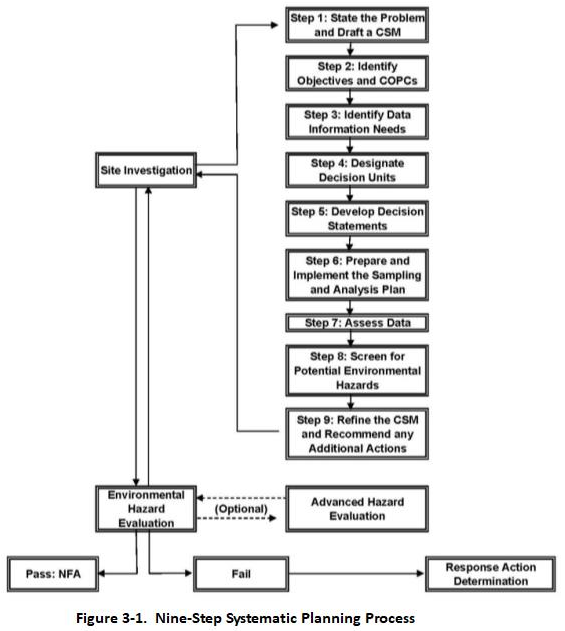
3.2 SYSTEMATIC PLANNING PROCESS
The Systematic Planning process consists of nine sequential steps designed to ensure that a well-thought-out workplan is prepared prior to the actual collection of samples in the field (Figure 3-1): (1) Define the site investigation scope and establish a preliminary conceptual site model (CSM); (2) Identify known or suspect hazardous chemicals; (3) Determine data information needs; (4) Designate DUs; (5) Develop DU decision statements; (6) Develop and implement sampling and analysis plan; (7) Assess the quality of the data; (8) Determine potential environmental risk/hazards and (9) Revise CSM and propose recommendations for next steps.
3.2.1 STEP 1: DEFINE SITE INVESTIGATION SCOPE & ESTABLISH PRELIMINARY CONCEPTUAL SITE MODEL
Review site history and available environmental data. Consult with past or current employees or other people familiar with operations at the site/facility. Review available information on past chemical use and known or potential releases. Consider preliminary screening of the site by collection of Multi Increment samples from a small number targeted DUs and use of field screening tools (e.g., portable XRF, PID, etc.,) to check for COPCs if previously collected sample data are not available. Prepare a preliminary assessment of potential environmental concerns at the site with respect to the types of chemicals suspected to have been released and current or anticipated future site use, including possible contamination of both soil and groundwater. Use this information to prepare a preliminary, CSM of contaminated soil and groundwater-related environmental hazards. Additional guidance on the preparation of a CSM is provided in Appendix B.
3.2.2 STEP 2: IDENTIFY SITE INVESTIGATION OBJECTIVES AND CHEMICALS OF POTENTIAL CONCERN
Use the information generated in Step 1 to develop specific site investigation questions related to risk and/or the optimization of remediation. Example questions directly related to risk include:
- What are the specific contaminants of concerns at the site?
- Does long-term exposure to contaminants in soil pose a chronic health risk to site occupants or construction workers or to ecological receptors?
- Do vapor emissions caused by temporary exposure of heavily contaminated soil pose a short- term, acute health risk to workers or nearby residents?
- Do volatile chemicals in contaminated soil pose a risk of vapor intrusion into overlying buildings and adverse impacts to indoor air?
- Do contaminants in soil pose risk of leaching concern and contamination of drinking water resources or ecological, aquatic habitats?
- Do contaminants in the soil pose a potential leaching concern for landfill disposal?
- Do contaminants in soil pose a risk of fire, nuisance odors, sheens on water, fouling of construction equipment or other concerns during current or future site activities?
Example questions related to remediation include:
- What are the lateral and vertical boundaries of contamination above levels of potential concern?
- Where is the main mass of the contaminant located?
- What is the mass of the contaminant in soil targeted for in situ treatment?
- How is the contaminant mass partitioned between free product (nonaqueous-phase liquid), dissolution in groundwater and sorption to soil particles?
Natural soil leaching concerns can be assessed by use of Synthetic Precipitation Leaching Procedure (SPLP Method 1312), soil column leaching method (Method 1314) or, for unpaved areas and aged releases, simple testing of groundwater (HDOH 2024). Leaching risks for soil that is to be disposed of in a landfill is assessed based on the Toxic Characteristic Leaching Procedure (TCLP). Both the SPLP lab protocol (USEPA 1994) and TCLP lab protocol (USEPA 1992) require testing of a minimum 100-gram subsample. Large particles included in the sample submitted to the laboratory should be included in the leaching test. Particles over 0.5 cm in diameter should be manually broken into smaller pieces in order to meet a Fundamental Error of approximately 15% (refer to Appendix D in Section 4). This is because the Investigation Question relates to leaching of contaminants from the soil as a whole. Note that the USEPA lab methods only require breakage of particles to only 1 cm diameter or less. This would result in an unacceptably large Fundament Error, however. Samples should not be milled, since this could bias the leaching tests high.
The latter set of questions are particularly important when the remediation goal is based on a targeted reduction in the mass of contaminant present (e.g., 80%) rather than cleanup to a concentration-based goal.
3.2.3 STEP 3: DETERMINE DATA INFORMATION NEEDS
Evaluate existing site data and determine if additional data or other information are needed. Data needs should be continuously re-evaluated and refined as more site information becomes available and potential hazards are identified.
For example, relatively immobile contaminants like lead, arsenic and organochlorine pesticides primarily pose direct-exposure concerns. Accurate assessment of risk might require additional testing of samples for parameters such as bioaccessibility. Nonvolatile, soluble contaminants like nickel salts and chlorinated herbicides can pose leaching problems and contamination of groundwater. This might require the collection of groundwater data. Volatile and soluble contaminants like petroleum hydrocarbons and chlorinated solvents can pose both leaching and vapor emission concerns. This might require the collection of soil vapor and if necessary indoor air data, if a significant vapor intrusion risk is identified (refer to TGM Section 7). Optimization of remediation can require a greater resolution of the lateral and vertical extent of high- concentration areas of contamination than might otherwise be necessary to simply assess risk.
Risk is always assessed based on the concentration of a contaminant for a designated exposure area and volume of soil as a whole. Sample collection must therefore be designed to directly provide the mean contamination concentration for a targeted DU area and volume of soil.
For example, “Does the true or “mean” concentration of lead for this 5,000 square feet (ft²) area of soil to a depth of four inches exceed the screening level for potential, direct exposure risk under current or future site conditions?” Note that all data for particulate matter represent a mean of the group of particles tested. Although retained for use in this document, use of the term “mean” is redundant and not strictly necessary. This question is addressed by the collection and testing of a representative sample from the designated area and volume of soil. The resulting data are then used to directly answer the investigation questions asked and determine the need for additional actions based on DU-specific “Decision Statement” formulated prior to the collection of samples.
3.2.4 STEP 4: DESIGNATE DECISION UNITS
Decision Unit areas and volumes of soil are designated for sample collection based on the site investigation questions. Examples of DU designation under different site scenarios are provided in Appendix C. Determine the location, size, shape and depth of Exposure Area and/or Source Area DUs based on the potential environmental hazards associated with target contaminants, the intended use of the site and anticipated remediation measures. Designate known or suspected contaminant source areas for individual testing in order to isolate the contamination and optimize remediation. These areas are generally set to tens of square meters to several hundred square meters in size. Designate one or more rings of Boundary DUs around the periphery of the suspected source area(s) to confirm the extent of contamination.
Divide the remainder of the site into Exposure Area DUs based on site usage for testing. If suspected source areas within the site are not identified, then consider dividing the entire site into Exposure Area DUs for testing. The locations and sizes of Exposure Area DUs are site-specific but are typically several hundred square meters in area.
3.2.5 STEP 5: PREPARE DECISION STATEMENTS/JUDGEMENTS
Use the sampling information determined in Step 3 and the DUs defined in Step 4 to write a decision statement specifying the contaminants to be measured and the corresponding measures to be taken during the decision-making process.
Example wording for decision statements includes:
“If the concentration of [chemical substance] in the targeted DU based on [MI sample data value] and analyzed using [analytical method] exceeds [value], then [required action]. If not, then [next steps].”
Actions in cases where published action (screening) levels are exceeded could include removal of contamination above default action levels, designation of areas for capping and long-term management, or development of alternative action levels in a site-specific risk assessment.
It is important that fixed decision statements be assigned to each DU at the beginning of the project and before samples are collected. The decisions statements should be agreed upon by all stakeholders in the investigation, including risk assessors, remediation experts and the overseeing regulatory agency and should consider the time allotted for completion of the project and the budget. Decision statements should be strictly followed when the sample data are obtained.
Decisions Units should be ideally designated at the scale necessary for final decision making from the start. Subdivision of original DUs for resampling after data are obtained and determined to exceed screening levels should be avoided (refer to Fact Sheet #2 in Section 4, Appendix A). This will minimize delays for completion of the project and avoid unanticipated problems due to changes in original plans. Followup subdivision of a site into smaller DUs might be unavoidable in some cases, however. Examples include cases where the responsible party is only willing to initially fund an investigation that focuses on the use of relatively large, Exposure Area DUs to assess risk. If one or more DUs fail action levels, then a decision will be made to abandon the project or proceed with a more detailed investigation. Responsible parties should be made aware of potential project completion delays if this approach is followed and weigh the pros and cons.
3.2.6 STEP 6: DEVELOP AND IMPLEMENT SAMPLE COLLECTION AND ANALYSIS PLAN
Prepare a plan for the collection, processing and testing of samples from the designated DUs. A detailed discussion of the elements of a sample collection and analysis plan is provided in the following sections and in the appendices.
When formulating a sampling plan, consider the challenges that could occur during sample collection, including:
- Availability of to-scale, detailed maps;
- Availability of facilities for equipment staging, decontamination and sample storage;
- Need to clear area of debris and vegetation before sample collection;
- Existing structures and other hindrances to access of targeted sample collection areas;
- Ground surface conditions (e.g., pavement);
- Topography;
- Subsurface debris, cobbles, boulders or bedrock that could inhibit drilling;
- Underground utilities;
- Overhead utilities;
- Depth to groundwater;
- Types of tools required to collect surface and/or subsurface samples;
- Total number of samples to be collected;
- Anticipated total sample collection and analytical costs;
- Laboratory sensitivity/reporting limits and tolerable QA/QC levels; and
- Reasonable allocation of funds.
Multi Increment sample collection methods are required to obtain reliably representative data for a targeted DU. A detailed discussion of the scientific basis of MI sample collection methods is provided in Appendix D. The inherent error in past, “discrete,” “grab” or “composite” sampling methods is discussed in Appendix E. The collection of MI samples from surface and subsurface soil is discussed in Appendices F and G, respectively. Additional guidance on the collection of samples from excavations and stockpiles, samples to be tested for volatile chemicals and the collection of sediment samples is provided in Appendices H through J.
Consult with the laboratory prior to submitting the samples for analysis. Request a copy of the laboratory Standard Operation Procedure for processing and analysis of MI Sample and ensure that they have experience. Discuss quality assurance measures to be carried out by the laboratory to ensure the data are representative of the samples provided. Require the laboratory to include a brief but concise summary of sample processing methods in the report, including the mass of the sample received and the mass of the subsample tested.
3.2.7 STEP 7: ASSESS DATA QUALITY
Review final sample collection and testing methods for consistency with the workplan and requirements for the collection of representative sample data. Review laboratory analytical performance data to assess data quality control associated with subsample testing. Refer to field and laboratory replicate sample data to evaluate the overall data precision (see Section 3.8). Ensure that analytical sensitivity and error are within agreement of the decision statements. Discuss how to address “non detect” result when the Method Reporting Limit or Detection Limit is above the action (screening) level or if a result is very close to the action level but the replicate RSD is higher than desired.
3.2.8 STEP 8: DETERMINE POTENTIAL ENVIRONMENTAL HAZARDS
After completing the data assessment, compare environmental data with environmental screening values or use the data to quantify risk in a risk assessment. Ensure that the risk assessment, also referred to as an Environmental Hazard Assessment, addresses all potential environmental concerns identified in Steps 1 through 3 of the planning process (refer to Section 13 and HIDOH 2017).
3.2.9 STEP 9: IMPROVE CSM AND PROPOSE NEXT ACTION PROPOSAL
Update the CSM based on the data collected and a more in-depth understanding of site conditions and potential environmental hazards. Use the revised CSM to identify any data gaps and determine the scope of work required to complete the site investigation. Prepare recommendations for additional actions when the investigation is determined to be complete and reliable.
Return to the Top of the Page
3.3 DESIGNATION OF DECISION UNITS
The need for remediation of contamination is driven by the identification of a significant risk to human health or the environment. The risk is identified and assessed by designation of risk-based areas and volumes of soil for testing, referred to as “Decision Units” or “DUs.” The proper designation of DUs of soil, sediment or any other environmental media for testing is a critical step in the site investigation process. Refer to Sections 6 and 7 of the TGM for discussion of DU designation approaches for water and air.
Decision Units represent the physical resolution of the site investigation necessary to address questions related to risk and optimization of potential remedial actions. These questions are prepared as part of the initial CSM. Designation of well-thought-out DUs with clear decision statements on how sample data are to be used helps minimize the need for additional sample collection and will expedite overall project completion. Improper designation of DUs during the site investigation stage of a project can result in delayed completion of the site characterization, an inaccurate assessment of risk and inefficient remediation.
A DU can be thought of as the total volume and area of soil that would ideally be sent to the laboratory for testing as a single mass. For example, this might include all of the upper four inches of soil in a 40,000 ft² playground for a total of 500 cyds of soil. In most cases, submittal of such a large mass of soil to a laboratory for extraction is not practical. As an alternative, a representative 1- to 2-kilogram (kg) sample of soil must be collected (Section 3.4). This sample is likely still too large for the laboratory to extract as a single mass and a second, representative subsample must be collected. As discussed in Appendix D, each step introduces error into the final data.
Most DUs are shaped like a thin table, with the length and width of the sides being far greater than the thickness. Such shapes require special attention to the sample collection method employed to represent the targeted area and volume of material. As discussed in Section 3.4, the sample must be collected by combining small masses of material from evenly spaced points throughout a DU. Testing of material from a single point or cluster of points will not generate reliable sample data for decision making.
Soil particle size is an important factor in the designation of DUs. As a default, the <2 millimeter (mm) fraction of material specifically defined as “soil” is normally targeted for testing (USEPA 1996b). This is the fraction of soil assumed to contain the main mass of contaminants and pose the highest environmental risk and, for the purposes of site characterization, is the actual DU. Testing of coarser or finer particle sizes might be required on a site-specific basis. For example, risk assessors might require data for the very fine fraction of soil specifically anticipated to adhere to young children’s hands (e.g., <250 micrometer [µm] or <150 µm; USEPA 2011d, 2016c). Larger particles, including cobbles and gravel as well as rock are not typically considered part of a DU and in general do not need to be tested beyond basic field screening (e.g., observance of stains, sheens when placed in water, odors, etc.). Consider the collection of soil gas samples to assess potential vapor intrusion or leaching risk and direct testing of groundwater for assessment of potential leaching risk.
Samples must be sieved to isolate the targeted particle size. Consider sieving in the field using a #10 sieve the soil is adequately dry or otherwise remove large particles by hand to reduce the mass shipped to the laboratory. If the initially designated DU does not contain soil within the targeted particle-size range, then no sample is collected. For example, if the <2 mm particle size is targeted but particles this small are not present in a stockpile of boulders then the DU of interest does not exist and no sample is collected.
A brief overview of common types of DU designation under different site scenarios is provided below. Additional examples of DUs are provided Appendix C.
Example scenarios include:
- Small- to medium-size commercial and industrial sites;
- New residential housing developments;
- Existing schools;
- Agricultural fields;
- Former industrial complexes;
- Petroleum facilities;
- Buried waste pits and subsurface contamination;
- Excavations and stockpiles; and
- Canals, ponds and streams.
The examples can also be applied to other types of sites, including mining areas.
Although some generalities can be made, the type, size, shape and number of DUs for a particular project is specific to that project and takes into consideration the past, present and future use of the site as well as the objectives of the party carrying out the investigation (refer to Fact Sheet #2 in Section 4, Appendix A). If a contaminant poses multiple potential environmental concerns (e.g., both direct exposure and leaching to groundwater), the smallest DU (i.e., the highest resolution) should be selected to investigate the soil. Different media within the DU (e.g., soil, groundwater, soil vapor, indoor air) should be sampled and tested separately as appropriate to address the investigation questions. If the investigation is being carried out purely for due diligence purposes as part of a property transaction and contamination is not known or suspected to be present, then testing of a relatively small number of large, Exposure Area size DUs might be adequate. The appropriate level of detail necessary to meet the short- and long-term needs of all stakeholders should be discussed with the responsible party prior to completion of the sampling plan.
Previously collected data for samples collected from single points, referred to as “discrete” or “grab” samples, during earlier stages of an investigation as well as unstructured “composite” samples can be used to assist in the designation of DUs for more comprehensive testing but should not be relied on for final decision making (Brewer et al. 2017a,b). A discussion of the limitations of these types of sampling methods is provided in Appendix E.
3.3.1 EXPOSURE AREA DUS
In risk assessment, an area of exposed soil that people regularly come in contact with and that could potentially be contaminated is referred to as an “exposure area.” Examples include parks, playgrounds and unpaved areas of commercial or industrial properties, landscaped areas, and construction worker areas (Figure 3-2; see also Section 4, Appendix C). Individual areas or in some cases the entire area are initially designated as Exposure Area DUs for characterization. Soil capped under a building or parking lot or soil in the subsurface that could be excavated and spread out in the future could be considered to represent future Exposure Area DUs.
Designate Exposure Area DUs based on current land use (e.g., the playground at a school or an unpaved work or eating area at a commercial or industrial site) or future use of the area (e.g., a proposed residential development). The upper two to six inches of soil is normally designated to assess current direct exposure risk. Testing of deeper soil suspected to be contaminated is often required to address potential disturbance of the soil in the future and redistribution on the surface.
If a known or suspect area of contamination is within an Exposure Area DU that could cause the entire DU to fail risk limits, then this area is normally isolated and independently tested as a Source Area DU (Section 3.3.2). This minimizes the need for retesting if a problem is discovered and optimizes the speed and efficiency of remedial actions. If the objective is simply to establish the presence or absence of risk for the Exposure DU as a whole, then subdivision characterization of subareas within the DU is not necessary.
3.3.2 CONTAMINATION SOURCE AREA DUS
Isolation and testing of known or suspect areas of heavy contamination to optimize remediation and reduce risk is an important part of most site investigations. Such areas, referred to as “Source Area” (or “Spill Area”) DUs, should be designated as separate DUs for investigation. Source Area DUs normally fall within and drive risk for larger Exposure Area DUs. Examples of source areas include former chemical storage areas, areas where chemicals were spilled or disposed of during factory operations, former waste pits and layers of buried waste (Figure 3-2).
Contamination designated as localized Source Area DUs at industrial properties often cover an area of only a few tens to hundreds of square meters and can be relatively shallow (thin). Examples include waste sand blast material, lead shot or lead-based paint in the upper few centimeters of soil. In other cases, contamination can extend to considerable depths, particularly for releases of solvents, petroleum or other liquids. The extent of subsurface contamination can also depend on whether the chemical was spilled at the surface, leaked from underground tanks and pipes or was intentionally buried. The suspected duration of the release should also be considered. Slow but long-duration leaks of liquid chemicals from underground tanks and pipes can result in very deep contamination extending to the water table. In case of dense, non-aqueous liquids (DNAPL), contamination can extend to well below the water table.
Exploratory boreholes and pits or trenches can be very useful for initial investigation of contamination in subsurface soils (see Section 3.3.4). Divide subsurface soil into separate DU layers for sample collection and analysis based on the information obtained in the CSM (Figure 3-4). If no obvious contamination or differences in soil type is identified in exploratory boreholes or pits and trenches but confirmation that subsurface soil is clean is required, then consider designation of multiple 0.5 m to 2 m DU layers for sample collection to a depth appropriate for the planned project.
Default DU volumes typically range from 100 to 400 m³ (approximately 100 to 400 cyds). Large DU volumes can be appropriate for due diligence testing of subsurface soil that it not anticipated to be contaminated. This might include, for example, relatively deep soil (e.g., DU-3 in figure) situated below an anticipated clean subsurface Boundary DU (e.g., DU-2) at a site where shallow, surface soil is impacted by releases of lead, PCBs or other relatively immobile contaminants (e.g., DU-1).
Obtaining precise, in situ concentration data for heavily contaminated subsurface soil might not be necessary in cases where the soil will be excavated or managed in place. Confirmation samples can instead be collected after initial remediation or to establish the boundaries of contaminated soil to be left on site. In other cases, high-resolution data for heavily contaminated subsurface soil might be required to estimate the mass of a contaminant and/or to help optimize the design of in situ remediation. Failure to initially obtain representative soil data is the leading cause of unsuccessful in situ remediation actions.
3.3.3 CONTAMINATION SOURCE BOUNDARY AREA DUS
Boundary DUs are used to surround and isolate areas of anticipated heavy contamination. The DUs are designated in anticipated clean or only moderately contaminated areas based on the initial CSM (Figure 3-5).
This helps to minimize the inclusion of otherwise clean soil in subsequent remedial actions and help control project costs.
The number and design of Boundary DUs designated as part of a project is site- and project-specific. In the case of the example depicted in Figure 3-5, the boundary between heavily contaminated soil and anticipated clean soil was clearly evident in the field and there was high confidence that the Boundary DUs would indeed be clean. In other cases, designation and testing of two or more rings of Boundary DUs might be desired in the event that the innermost DUs fail screening levels.
Vertical delineation of contamination should similarly be determined based on designation and testing of vertical Boundary DU layers. If necessary, the extent of subsurface contamination can be initially approximated using exploratory borings, pits or trenches (refer to subsurface investigation guidance in Appendix G). Limitations of testing of single cores of soil and the potential for both false negatives and false positives with respect to the large-scale assessment of risk and remediation needs must be considered. More reliable DU sampling methods and data should be used to confirm the boundaries of identified or suspect source areas. Designate boundary DU sizes in a manner that will optimize potential remedial actions but avoid the need for remobilization for collection of additional samples if action levels are failed.
3.3.4 EXCAVATIONS AND STOCKPILES
Detailed guidance on testing of excavation sidewalls and stockpiles is provided in Section 4, Appendix H. Guidance on testing of stockpiles or other sources of imported fill material is provided in Section 4, Appendix P.
The walls and floor of an excavation should be designated as separate DUs for sample collection (Figure 3-6). Lateral and vertical Boundary DUs are designated to confirm the removal of a source area of contaminated soil. Multiple DU layers may need to be designated within a DU wall to target specific layer intervals of contamination. It may also be necessary to divide the floor of the excavation into multiple DU areas to confirm the vertical cleanup of contaminated soil. Such decisions must be made on a site-specific basis.
The concept of Exposure Area and Source Area DUs also applies to testing of stockpiles of excavated soil. Designation of DUs for stockpiles, in contrast, based on the risk-based volume of soil associated with the anticipated reuse, for example reuse as fill in a residential redevelopment project (resident exposure risk) or disposal at a landfill and reuse for daily cover (worker exposure risk). Example risk-based volumes of soil are presented in Table 3-1. Additional guidance on the designation of DUs and the collection of samples from stockpiles is provided in the appendices. This approach can also be used for testing of stockpiles of dredged sediment that is proposed for reuse as fill material.
Table 3-1. Example default DU volumes for stockpiles.
| Receiving Site Land Use | ¹Default DU Volume | Notes |
| Unrestricted Use (includes small parks and low-density, residential developments with individual yards) | 100 cyds | Assumes approximately 5000 ft² reuse exposure area and 6″ placement thickness. |
| Schools and High-Density Residential Developments | 400 cyds | Assumes approximately half-acre exposure area and 6″ placement thickness. |
| Commercial or Industrial use only (including agricultural lots) | 400 cyds | Assumes approximately half-acre exposure area and 6″ placement thickness. |
| 1. Testing of 100 cyd DU volume of soil is anticipated in most cases to identify potentially significant vapor intrusion and/or leaching concerns. Use of smaller DUs volumes as well as the collection of soil vapor data and/or used of laboratory-based methods to assess leaching risk might be required on a case-by-case basis. Note that this updates and takes precedence over recommendations to use a 20 cyd DU volume for assessment of leaching risks in the 2017 HIDOH Clean Fill guidance. | ||
Larger DU volumes up to several thousand cubic yards might be acceptable for stockpiles of soil or dredged sediment when the origin of the soil is well known and there is no reason to suspect significant contamination. Examples include excess soil generated during construction on previously undeveloped land or dredged sediment from areas not susceptible to contamination. Some level of minimal testing in this case is often desirable for legal due diligence purposes.
When investigating stockpiles, large stockpiles should be separated or split into separate piles based on soil type, source, potential for contamination, potential environmental concerns associated with targeted chemicals (e.g., direct exposure or leaching) and proposed reuse of the oil. Stockpiles of soil are normally flattened and divided into DU volumes for testing using the same concepts of source areas and exposure risk as applied to testing of in situ soil (Figure 3-7). Alternative methods for sample collection where pile cannot be flattened are discussed in Appendix G.5 and Appendix H. This includes incremental testings and clearing of soil and accessible faces of a stockpile and excavation of small “windows” and trenches to access interior areas of a pile.
Consideration of the “fluff factor” and larger volumes can be made for stockpiled ex situ soil that will be compacted during use as fill material. Allowances for larger DU volumes can be made for deeper material not known or suspected to be contaminated (e.g., native soil) as well as sediment to be dredged from areas that lack known sources of potentially significant contamination, where testing is primarily for due diligence purposes. Refer to Appendix H for additional guidance.
Figure 3-7. Example flattening of a soil stockpile and division into risk based DUs for sample collection. Trenches, pits or other types of “windows” can be cut into stockpiles to assist in sample collection when space is not available for flattening the pile.
3.3.5 SEDIMENT DECISION UNITS
Decision Unit and Multi Increment Sample investigation methods are used for characterization and remediation of contaminated sediment in a similar manner as described for soil. Examples include the investigation of direct-exposure risk to benthic and aquatic organisms and in situ or ex situ characterization of dredge material for reuse as fill in upland areas or for offshore or onshore disposal.
Designate DUs based on risk to ecological receptors or optimization of anticipated dredging or in situ remediation actions. Ecological risk is assessed based on exposure to benthic organisms as well as factors such as particle size for open water disposal. Human health risk associated with upland reuse of dredged sediment as fill material in the same manner as described for stockpiles and Exposure Area DUs.
Example investigation questions that can be used to designate DUs for assessment and sample collection include:
- Is the sediment within this specific DU area of the lake, river, canal, etc., contaminated above levels of potential concern?
- What is the lateral and vertical extent of contamination above levels of potential concern?
- Is contamination restricted to specific depositional areas of sediment?
- Do risk-based DU volumes of sediment proposed for dredging or already dredged and stockpiled material meet comparable risk-based screening levels for proposed reuse in upland areas?
Specific areas and volumes of sediment must be assigned to each investigation question. In some cases, a single DU might be adequate. In other cases, designation of multiple DUs might be required.
Dredging projects can generate very large volumes of sediment desirable for use as fill material in upland areas. DU volumes up to 800 cyds or greater might be acceptable for testing of sandy sediment not located in the proximity of a contaminant source and lacking in significant, fine-grained material potentially associated with contamination imported by currents. Examples include dredging of mobile sand bars in rivers and tidally influenced areas. Fine-grained sediment in harbors, canals and similar low-energy bodies of water that are highly susceptible to releases of contaminants will normally require testing of much smaller DUs to optimize costs associated with offshore or onshore disposal or in situ remediation.
For proposed upland reuse of dredged material, DU volumes should reflect the potential exposure scenario in relation to the proposed area size and placement thickness. For example, the dredged sediment is proposed to be reused as fill material at a planned one-acre soccer field. In this case, the exposure is assumed to be primarily a concern for the upper 6” of soil, for a total approximate volume of 400 cyds. Larger DU volumes might be acceptable depending on reuse area and assumed uniformity of contaminants within the sediment (refer to case studies in Appendix C).
As discussed in the harbor dredging case study in Appendix C, sample collection can be carried out in situ, during dredging or after the dredged material has been placed in stockpiles. The most optimal strategy for a specific project will depend on factors that include accessibility and availability of cost-effective methods for in situ sample collection and the availability of space for stockpiling as well as time constraints for ex situ sampling.
Return to the Top of the Page
3.4 SAMPLING AND ANALYSIS PLANS
3.4.1 SAP OUTLINE
The Sampling and Analysis Plan (SAP), developed during Step 6 of systematic planning, specifies the final design and configuration of the environmental measurement effort required to resolve issues and questions stated in the systematic planning steps (Steps 1-5). The SAP is a comprehensive document that would enable an experienced field sampling team unfamiliar with the site to come in and examine the site and collect the required samples and field information. The SAP designates the types and quantities of samples or monitoring information to be collected; where, when and under what conditions they should be collected; the variables to be measured; and the Quality Assurance/Quality Control (QA/QC) procedures to ensure that sampling design and measurement errors meet the tolerable decision error specified.
The QA/QC procedures are described within the Quality Assurance Project Plan (QAPP), which is included within the SAP. The site-specific Health and Safety Plan is also included as part of the overall SAP (alternately, the Health and Safety Plan can be presented with the SAP in a site Work Plan). The SAP must be flexible and dynamic to deal with unexpected discoveries or circumstances that may be encountered during the site investigation. To ensure appropriate characterization of the site and to minimize the need to perform additional sampling, it is recommended that SAPs be reviewed and approved by the HEER Office. In addition, it is important to consult with the laboratory while developing the SAP to ensure objectives are in alignment with chosen laboratory practices, and to provide contingencies for matrix problems that may occur. Important among such issues to discuss with the laboratory are expectations for storing remaining portions of MI samples that have been analyzed, until site sampling decisions are completed. Based on initial data analysis or new information, additional analyses may be conducted from stored bulk MI samples rather than having to mobilize and collect additional samples in the field.
The suggested outline for the SAP is as follows:
| I. Introduction | VI. Description of Sampling Activities |
| II. Site Background | VII. Analytical Methods |
| a. Site description | VIII. Quality Assurance Project Plan |
| b. Site characteristics | IX. Documentation and Reporting |
| III. Investigation History | X. Schedule |
| IV. Site Investigation Objectives | XI. Health and Safety Plan |
| V. Scope of Work | XII. References |
More detailed information regarding the outline, format, and required content of the SAP is presented in https://health.hawaii.gov/heer/tgm/section-18/” target=”_blank” rel=”noopener noreferrer”>Section 18.
3.4.2 SAMPLE COLLECTION STRATEGY
A sampling strategy should reflect the approach that will best meet investigation objectives within acceptable uncertainty limits, with consideration taken for efficient use of time, money, and human resources. Section 4, Appendix D discuses sample collection strategies for soil and sediment.
The HEER Office strongly encourages the use of Multi Increment/Decision Unit strategies to investigate contaminated soil. Multi Increment samples are collected using a probabilistic sampling theory and involve the collection of a large number of increments (30-100) from within the target DU. Each increment is made up of approximately 5 to 50 grams of soil. The increments are combined to form a single, Multi Increment sample for the DU. A detailed discussion of Multi Increment sampling approaches is provided in Section 4, Appendix D.
See Section 6 for sample collection strategies for groundwater, and Section 13 for information and references regarding ecological risk evaluations.
3.4.3 HEALTH AND SAFETY PLANS
Hawai’i hazardous substance release sites fall under the definition of “uncontrolled hazardous waste sites” pursuant to Occupational Safety and Health Administration (OSHA) Hazardous Waste Operations and Emergency Response (HAZWOPER) Title 29 Code of Federal Regulations (CFR) Section 1910.120(a)(1). A health and safety plan (HASP) is required under Title 29 of the Code of Federal Regulations, Section 1910.120 (Hazardous Waste Operations and Emergency Response), which includes a requirement for a hazard communication program meeting the requirements of 29 CFR 1910.1200. Like rules were adopted under Hawaii Administrative Rules Title 12 Department of Labor and Industrial Relations Subtitle 8 Hawaii Occupational Safety and Health Division Part 2 General Legal and Administrative Provisions for Occupational Safety and Health Chapter 60 General Safety and Health Requirements and Hawaii Administrative Rules Title 12 Department of Labor and Industrial Relations Subtitle 8 Division of Occupational Safety and Health Part 8 Health Standards Chapter 203.1 Hazard Communication. The Health and Safety plan is typically a part of the SAP (or alternately, part of the site Work Plan). The HEER Office recommends that an employer develop a written Health and Safety Plan, which includes the following elements:
- An organizational structure
- A comprehensive work plan
- A site-specific health and safety plan
- A health and safety training program
- A medical surveillance program
- Standard operating procedures for health and safety
- Any necessary interface between general program and site-specific activities
The OSHA HAZWOPER Standard, Title 29 CFR 1910.120, requires that personnel working in and around hazardous waste have a site-specific HASP and competent safety officers to enforce health and safety rules. OSHA has determined that employees must be trained if they work in proximity to hazardous chemicals with a potential for release or substantial threats of release, without regard to the location of the hazard.
An OSHA-certified 40-hour class focusing on HAZWOPER training is required for those who are performing regular work on hazardous waste sites; an annual 8-hour refresher course is required to maintain the certification achieved through this training. An OSHA-certified 24-hour course is required for those who have occasional exposure to hazardous waste. In addition, an 8-hour course is required for supervisors and management personnel who oversee hazardous waste projects. The amount of training required is contingent upon an employee’s responsibilities and involvement with hazardous materials; these must be clearly established by the employer and communicated to the employee(s). The HEER Office does not approve Health and Safety Plans but does require that one be in place for field activities at hazardous chemical release (or suspect release) sites. Contact the Hawai`i Division of Occupational Safety and Health (HIOSH) for detailed information on HASPs and organizations offering HAZWOPER training.
3.4.4 QUALITY ASSURANCE PROJECT PLANS
Data acceptance criteria, developed during Step 5 of systematic planning, are presented in the Quality Assurance Project Plan (QAPP) which is the formal project document that specifies the operational procedures and QA/QC requirements for obtaining environmental data of sufficient quantity and quality to satisfy site investigation objectives. The QAPP is required for all data collection activities that generate data for use in decision-making. It contains information on project management, measurement and data acquisition, assessment and oversight, and data validation and usability. The QAPP integrates the DQO, the data collection design, and QA/QC procedures into a coherent plan to be used for collecting data that are of known quality and adequate for their intended use. The QAPP is typically presented as part of the SAP (Step 6 of systematic planning) and should include the following elements:
- Quality assurance (QA) objectives for measurement
- Sample chain of custody
- Calibration procedures
- Analytical methods
- Data reduction, validation, and reporting
- Internal quality control (field and laboratory checks)
- Performance and system audits
- Preventative maintenance
- Data measurement assessment procedures (precision, accuracy, and completeness)
- Corrective actions
Participation of the laboratory that will be utilized is important to ensure capabilities are agreed upon and not assumed. Other considerations such as potential changes to cleanup processes, lab filtration, etc. should be discussed ahead of time when potentially contaminated samples are collected.
More detailed information regarding the outline, format, and required content of the SAP, which includes the QAPP, is presented in Section 18.
Additional information regarding the development of a QAPP is available in the Uniform Federal Policy for Quality Assurance Project Plans (USEPA/DoD/DOE 2005), Guidance for Conducting Remedial Investigation and Feasibility Studies under CERCLA (USEPA 1988), and Guidance for Quality Assurance Project Plans (USEPA, 2002g). In addition, Data Quality Assurance and Quality Control procedures are discussed in detail in Section 10.
Return to the Top of the Page
3.5 SITE INVESTIGATION REPORTS
Accurate and thorough documentation of the sample plan design, sample collection and handling procedures, laboratory analyses, data assessment, and a summary of the data collected are crucial to the site investigation. The laboratory selected should adhere to a comprehensive Quality Assurance Plan and SOPs for sample analyses. The HEER Office strongly encourages active communication, including draft report reviews and subsequent meetings or conference calls, to prevent costly remobilizations to collect additional data. The following reports (and major elements) are typically prepared and submitted to the HEER Office for review.
- Sampling and Analysis Plan
- Sampling design
- Preliminary Conceptual Site Model
- Preliminary site investigation objectives and DQO
- QAPP
- Safety and Health Plan
- Site Investigation Report
- Site history
- Site investigation objectives (including DQO)
- Selection of Decision Units, including replicates
- Figures displaying all DU locations on site
- Identification of information needs
- Sample collection and analysis methods
- Summary of analytical results
- Data assessment
- Summary of extent and magnitude of contamination
- Preliminary Environmental Hazard Evaluation
- Conclusions and recommendations
Additional guidance on report formats and content is presented in detail in Section 18. The HEER Office requires that the lateral and, as needed, vertical extent of soil and groundwater (and in some cases soil gas) contamination be clearly depicted on to-scale maps and cross sections of the site. Shading or other graphics should be used to depict DUs suspected to be contaminated above levels of potential concern. This information is then used in the Environmental Hazard Evaluation to identify specific environmental hazards posed by the identified contamination as well as the specific areas of the site where these hazards are present (see Section 13). The results of the preliminary Environmental Hazard Evaluation may require that additional data be collected at the site (e.g., soil gas data to evaluate potential vapor intrusion concerns) or that additional tests be carried out on existing samples. After all environmental hazards are adequately identified, delineated and evaluated, the final Site Investigation and Environmental Hazard Evaluation reports are used to support and assist in the development of appropriate response actions.
Not all projects will require that formal sampling plans and related reports be submitted prior to initiating site investigation activities; this will vary from site to site and should be discussed with the overseeing project manager in the HEER Office.
Return to the Top of the Page
3.6 DECISION UNIT CHARACTERIZATION
3.6.1 USE OF MULTI INCREMENT SAMPLES TO REPRESENT DUS
Risk is always assessed based on the “true” or “mean” concentration of the contaminant in each subject DU (USEPA 1987, 1988, 1989b, c, e, f, 1991g, 1992c, 2014f). The objective of sample collection is therefore always to estimate the concentration of the contaminant for the targeted DU volume of soil or sediment as a whole. Ideally, the entire DU volume of soil would be removed, taken to a laboratory for testing and the concentration of the subject contaminant for the volume of soil as a whole determined. This is not normally possible, however, and a representative sample of the targeted area and volume of soil must instead be collected.
Obtaining reliable data requires that both the sample in the field is representative of the targeted DU area and volume of soil and that the subsample collected for testing at the laboratory is representative of the sample submitted. This is most efficiently accomplished through the collection of a single MI sample from each DU (HDOH 2016). A sample is prepared by collecting and combining a large number of small masses or “increments” of material throughout the entire DU area and volume of soil or sediment (Figure 3-8). The science background and use of MI sample collection methods is based on Pierre Gy’s Theory of Sampling (Pitard 2019). A detailed review of Gy’s sampling theory is provided in Appendix D.
Detailed guidance on the collection of MI samples from surface and subsurface soil as well as excavations and stockpiles is provided in Appendices F through I. The collection of sediment samples is discussed in Appendix J. Processing and testing of MI samples is discussed in Appendix K.
The largest source of error in environmental data is associated with the collection of soil or sediment samples in the field, followed by the collection of subsamples for testing at the laboratory (Pitard 2019; Esbensen 2020). Error associated with analysis of the subsample by the laboratory is typically small by comparison. Field sample and laboratory subsample collection error is controlled by ensuring that an adequate number of increment collection points are utilized and that an adequate total mass of material is collected (refer to Appendix D).
Strong attention to detail is required to collect, process and test a sample in a manner that ensures representative data. Independent replicate samples are collected from a portion of the DUs tested for a specific project (Appendix L). Types of replicate sample data that should be generated for all projects include (see Section 3.6.5):
- Field Sample Replicates (minimum two from at least one DU; tests the overall precision of the total sample collection, processing and analysis methods);
- Field Subsample Replicates (minimum two from at least one DU Layer; tests the precision of subsampling methods required to reduce sample mass for samples prepared from subsurface borings);
- Laboratory Subsample Replicates (minimum two for at least one sample if subsampling of increments is carried out in the field as often required for subsurface investigations; tests the precision of method used by the laboratory to collect a subsample from a field sample for analysis); and
- Laboratory Analytical Replicates (minimum one for each set of samples; tests the precision of the equipment used to analyze a subsample).
Although the collection and testing of field and laboratory replicates adds to the cost of an investigation, the results are critical to demonstrate the reproducibility of the data and defensibility of decisions made. Sample data can only be assumed to be truly representative if the samples were collected properly in the field to begin with (refer to Appendix D).
Additional information on General Field Operations is provided in Appendix M, including field documentation, equipment preparation and decontamination, disposal of investigation derived waste and completion of field work. Common mistakes made in the field and laboratory and that can be reflected by highly variable replicate sample data are discussed in Appendix N. Guidance on the investigation of contaminated soil and sediment under the Toxics Substances Control Act (TSCA) is provided in Appendix O.
3.6.2 SAMPLE MASS, INCREMENT NUMBER, QUALITY AND DISTRIBUTION
Field Sample and Laboratory Subsample Mass
Gy’s Theory of Sampling and experience in the field indicates that a minimum total field sample mass of 1 to 3 kg is necessary to reliably represent the tens, hundreds or even thousands of metric tons of soil incorporated into a DU (Brewer et al. 2017a, b; Walsh 2020). This is intended to address both potential errors associated with the physical nature of the soil or sediment as well as error associated with the collection of sample increments in the field (refer to Appendix D). The mass of increments should remain consistent between collection points and be adequate to achieve the target bulk sample mass after combination into a single sample. For example, the preparation of a 1 to 3 kg 50-increment sample requires an increment mass of 20 to 60 grams.
The final bulk mass applies to the targeted soil particle size and should consider potential sample loss from sieving and the dampness of the soil or sediment. This is not normally an issue for soil but can require the need for a larger sample of saturated sediment in the field, particularly if the sample contains a large amount of fined-grained, clayey material.
A minimum sample mass of 300 grams is recommended for samples to be tested for volatile chemicals (Appendix I). Samples might be prepared, for example, by combination of 60, five-gram increment plugs from excavation sidewalls or from subsurface cores (Appendix I). A smaller bulk sample mass is acceptable due to an expected, more uniform (but still heterogeneous) distribution of liquid volatile contaminants in soil within source areas. Larger samples to be tested for volatile chemicals should be collected, if possible, to increase the representativeness of the data. Refer to Appendix I for guidance on alternatives to the collection of soil samples for assessment of risks posed by volatile chemicals.
Alternative preservation methods for soil samples to be tested for volatile chemicals are discussed in Appendix I. Note that soil data for volatile compounds are most efficiently used to estimate the mass of the contaminant present within a DU as a tool to assist in the design of remedial efforts. The primary environmental risks associated with volatile chemicals are vapor intrusion into overlying buildings and/or leaching of the contaminant into underlying groundwater. In both cases, the collection of soil gas sample data can serve as more directly applicable alternative to soil sample data, provided that soil gas-based action/screening levels are available or can be developed for comparison (refer to Section 13 of the TGM; see also HIDOH 2017).
An ideal analytical subsample mass of 30 grams is recommended to control Fundamental Error associated with <2mm particle size material as well as error associated with the collection of material from a processed sample. If a maximum 10-gram subsample is necessary, then consider the collection of additional subsample replicates in order to better assess error in the data (refer to Section 3.6.5). A ten-gram subsample is adequate for <250µm material. Sample processing and subsample collection methods, normally carried out at a fixed laboratory, are discussed in Appendix K.
Number of Sample Increments
The number of increments necessary to reliably represent a targeted DU area and volume of soil or sediment depends on the distributional heterogeneity of the contaminant within the DU. Statistical analysis of data from field studies indicate that as few as 30 increments per sample can be adequate for characterization of soil impacted by airborne or waterborne contaminants, including stack emissions from a smelter, application of water-based pesticides to field areas or testing of sediment (Brewer et al. 2017a, b; Walsh 2020). A minimum of 75 increments per sample is recommended for cases where the contaminant is present as small nuggets or chips. Examples include polychlorinated biphenyls (PCBs) derived from construction debris or waste oil, fragments of lead-based paint and fragments of lead related to munitions. A default minimum of 50 increments per sample is recommended for the investigation of soil where the nature of the contamination is uncertain.
A larger number of increments might be necessary due to the sample collection method used. For example, the collection of 60 plugs/increments of soil are required to meet the minimum mass requirement of 300 grams if a small syringe is used to collect five-gram plugs of soil from an excavation floor. As an alternative, two side-by-side, five-gram plugs could be collected and combined as a single increment from each of 30 points in the DU face.
The sample increment requirements apply to both surface and subsurface soil and sediment. The fact that the targeted DU layer of soil or sediment is covered with other soil or sediment (or water) does not alter the need to adequately capture and represent distributional heterogeneity. Consider designating a larger number of boring/increment locations than needed for adequate sample preparation as part of subsurface investigations where areas of refusal due to large rocks or other interferences are anticipated. Nonetheless, achieving an optimal number of increments per sample for testing of subsurface samples might in some cases not be possible due to access and budget limitations. Consider designated extra core increment collection points at sites where refusal in some areas is anticipated due to the potential presence of rock, subsurface utilities or buried debris. As discussed below and in Appendix G, data based on samples prepared from less than 30 increments should be considered suspect. Follow-up testing should be carried out if the soil is excavated or otherwise exposed in the future.
If a significant discrepancy between replicate sample data is observed and determined to be based on field error, then the collection of new samples might be required (refer to Appendix L). If this is the case, the number of increments collected per sample and the total mass of the sample should be increased. The original DU could in theory be subdivided into smaller DUs for retesting in order to better isolate subsequently identified areas of known or suspected higher contamination. Redesignation of DUs after initiation of a project is discouraged, however. Designation of DUs should be based on risk or optimization of anticipated remedial actions, not simply in an effort to improve sample data quality.
Increment Quality
The physical collection of sample increments is briefly reviewed in Sections 3.4.4. Detailed guidance on the collection of sample increments in the field under different site and contaminant scenarios is provided in Appendices F through I. The collection of subsamples at the laboratory for analysis is discussed in Appendix K.
The quality of individual increments depends on the shape, mass and uniformity of each increment. Increments should be core shaped and of sufficient mass to meet the minimum target bulk MI sample mass requirement. Ideal increments are core shaped and collected from the entire thickness of the targeted DU layer.
Increment Spacing and Location
Spacing increment collection points evenly throughout the DU both laterally and vertically is important to ensure that sample data are representative and reproducible. A systematic random method of increment placement is recommended (Figure 3-9). Increment locations are arranged in a grid cell pattern with a fixed interval, starting from a random point in one corner the DU. Subsequent increments are collected from the same location in all remaining cells. This applies to the collection of both surface and subsurface increments. Refer to Appendix N for common problems associated with increment spacing in the field.
An initial estimate of adequate increment spacing is calculated taking the square root of the DU area divided by the targeted number of increments to be collected:
This simulates division of the DU into individual, increment collection cells, with a single increment collected from the center of each cell. After calculating the square root of this area, the length of each side of the cell is obtained (assuming square cells).
Refer to Table 3-2. For example, assume a 5000 ft² DU and the desired collection of a 50-increment, sample. The calculated increment spacing is 10 feet. This reflects the assumption that the DU is divided into 50 square cells with 10 foot sides and area of 100 ft². A sample is prepared by collecting an increment from a random point within a cell, such as the center and then 10 feet parallel to the DU boundary to the same point in the adjacent increment cell. This is continued until an increment has been collected in each of the 50 hypothetical cells. The increments are progressively combined into a single bulk sample as they are collected.
Table 3-2. Example Increment spacing based on DU size and target number of increments (meters).
| # Increments | Decision Unit Area (acres) | ||||||||
| 0.10 | 0.20 | 0.25 | 0.50 | 1.0 | 2.0 | 3.0 | 4.0 | 5.0 | |
| 30 | 12 | 17 | 19 | 27 | 38 | 54 | 66 | 76 | 86 |
| 40 | 10 | 15 | 16 | 23 | 33 | 46 | 57 | 66 | 73 |
| 50 | 9 | 13 | 15 | 21 | 29 | 41 | 51 | 59 | 66 |
| 75 | 8 | 11 | 12 | 17 | 24 | 34 | 41 | 48 | 54 |
| 100 | 7 | 9 | 10 | 15 | 21 | 29 | 36 | 41 | 46 |
This approach applies to both rectangular and irregular-shaped DUs. The spacing can be adjusted as needed to help establish a manageable grid for sample collection, provided that an overall systematic random increment collection method is maintained. Examples of proper and improper increment collection patterns are included in Appendix F.
3.6.3 SAMPLE COLLECTION AREA PREPARATION
Remove Surface Debris and Vegetation
Site preparation activities are discussed in Appendix F. A site inspection should be performed prior to mobilizing to collect samples to determine if debris or vegetation needs to be removed. This might include temporary removal of stored material, automobiles and other equipment as well as cutting grass and removal of other low vegetation.
If surface soil is targeted for sampling, then care must be taken not to disturb the soil immediately below the root zone of the vegetation during site clearing activities. If soil within the root zone is targeted, then care must be taken to only remove vegetation directly above the ground surface. Bulldozers or similar equipment should normally not be used to scrape the ground surface since contaminated soil could become mixed with grubbed material. For testing of very large, heavily vegetated areas, consider surveying and clearing narrow, equally spaced transects that correspond to the desired spacing of increments for the DU.
Clear Underground Utilities
Sources for information on the presence of underground utilities, tanks, waste burial pits or other features of the site should be reviewed. These underground features and utilities could interfere with subsurface sample collection or pose a danger to either the utilities or samplers.
Example sources of information include:
- Information provided by public utility companies;
- Call before you dig (https://call811.com/);
- Maps that depict underground water, sewer, electric, gas, fiber optic and other utilities, as well as irrigation lines, buried tanks and pipeline, former building foundations, etc.;
- Interviews with site workers; and
- Field observations if manhole covers, vent pipes, piping and other signs of possible subsurface infrastructure or buried material.
The specific location, arrangement and depth of underground utilities must be determined to the degree possible and marked at the surface to assist in the placement of subsurface borings. Toning methods such as electro-magnetic/radio frequency technology should be considered for sites where subsurface utilities are suspected but the exact locations are unknown.
3.6.4 COLLECTION OF SOIL SAMPLES
Detailed guidance on the collection of MI samples from surface soil, subsurface soil, excavations and stockpiles, sediment and the collection of samples to be tested for volatile chemicals is provided in the Appendices F through I. A brief overview of sample collection methods is provided below. For the purposes of this guidance, the term “soil” is applied to any type of unconsolidated particulate matter. Larger particles, including cobbles and gravel as well as rock are not typically considered part of a DU and in general do not need to be sampled beyond basic field screening (.e.g., observance of stains, sheens when placed in water, odors, etc.).
Proper selection of sampling tools is crucial. The tools utilized must ensure that the soil increments are core- shaped or otherwise have no depth bias to the extent possible and that the mass of individual increments collected is relatively equal. The total mass of the combined increments must be sufficient to achieve the target minimum mass of the MI sample to be collected. “Discrete” samples or “composite” samples that do not meet the strict quality criteria of MI samples should never be used for final decision making purposes (refer to Appendix F).
Be aware that not all laboratories are set up to carry out MI sample processing and analysis. Contact the laboratory ahead of time to discuss sample processing and analysis requirements. Ensure that the lab can meet the requirements for sample preparation and minimum sample mass. If available, obtain a copy of the laboratory’s Standard Operation Procedure for management of MI samples for your records.
Surface Soil
A detailed discussion of methods and tools to collect MI samples from exposed surface soil under different site conditions is provided in Appendix F. The sample collection team progressively moves through the DU to individual increment collection points until the preparation of the sample is completed (Figure 3-10).
Increment collection can range from relatively easy for loose, fine-grained soil exposed at the surface to very difficult for gravelly or hard-packed soil. A variety of tools can be used to collect surface soil samples. The most appropriate tool is selected based on soil type, compactness, rock abundance and targeted increment depth.
Soft Soil. For soft soil, samples are usually collected using sampling tubes or similar manual coring equipment (depicted in Figure 3-10). Small-diameter sampling tubes (one to two inches) are simple, fast and efficient and suitable for a one- or two-person field team. Larger-diameter sampling tubes (more than two inches) will in most cases result in increment masses larger than the amount needed to prepare a 1 to 3 kg bulk sample. While larger samples might be more representative, secondary subsampling in the field could be required to prepare a final sample mass that can be managed by the laboratory. This will introduce additional error into the resulting data.
Loose, dry soil. A flat-bottomed trowel or similar tool might be required for the collection of increments from loose, dry soil (e.g., dry sand or silt). The tool should have a straight, front edge and perpendicular, square sides.
Semi-compact, fine-grained soil. For semi-compact, fine-grained soils, a power drill equipped with an auger bit that has a hollow center flute can significantly expedite the collection of increments (e.g., SpeedBore bits; refer to Appendix F). A one-inch hollow auger drill bit produces 30 to 50 g of soil for every six inches (15 cm) of drilling. The use of drills with standard winged bits should be avoided since they are less efficient at soil removal and can result in oversized increment masses.
Moderately compacted soil. A hand-held, battery-powered drill equipped with a small, spade bit can be very efficient for loosening soil at increment collection points and collecting samples in moderately compacted soils.
Significantly compacted or gravelly soil. A hammer drill with a cement bit or spade bit connected to a portable generator or a manual pickaxe or heavy rock hammer is usually required for the collection of increments from significantly compacted or gravelly soils. In these cases, the bit is used to create an opening and use a trowel to collect an increment from the exposed sidewall. See Appendix F for addition guidance and examples.
Subsurface Soil
A detailed discussion of methods and tools to collect MI samples from subsurface soil is provided in Appendix G. Identical requirements for the collection of high-quality, representative samples from surface soil apply to subsurface soil, with the added field factor that overlying soil must be penetrated to collect increments and prepare samples. The subsurface soil is first subdivided into individually targeted DU layers (Figure 3-11). Ideally, a 1 to 3 kg, 30- to 75-increment sample is collected from each layer.
When site conditions allow, direct-push drill rigs are very efficient for the rapid collection of samples from subsurface soil (depicted Figure 3-11). The rigs can also be used to collect soil gas and/or groundwater samples, if needed. Each core extracted from a targeted DU Layer represents a single increment for that layer, similar to the collection of individual, core-shaped increments from surface soil.
Use a measuring tape and/or soil characteristics used to designate each DU layer to identify targeted DU layers in a core increment (Figure 3-12). The mass of a single core increment is usually too large to be used for the preparation of a manageable sample. The field collection of a representative subsample of adequate mass (e.g., 20 to 60 g) from each DU layer increment is therefore required. For example, this can be achieved by collection of a long, thin wedge from the entire length of the DU layer increment. This might not be possible for gravelly soils. An alternative is to collect four to ten, evenly spaced, five-gram plugs of soil along the entire interval of the increment (depicted in Figure 3-12). Core increment subsamples corresponding to the same DU layer are combined on site to prepare an MI sample for that layer, similar to the approach used to prepare a sample of surface soil.
Be aware that direct-push methods often compress soil and the resulting core may be shorter than expected, if so scale the size of each DU depth accordingly. Also avoid the first inch or so of soil in each DU depth interval as it tends to contain slough from the previous DU interval.
A backhoe can be used to dig potholes or trenches at increment collection locations for testing of soil within approximately 1.5 m of the surface (Figure 3-13). This approach might be necessary for soil that contains large rocks or other obstacles where a direct-push rig otherwise cannot be used. An increment can be collected from each targeted DU layer by using a trowel to scrape a continuous mass of soil from the exposed excavation wall. Samples must be collected with care to ensure that the spacing between increments is equal both laterally and vertically across the DU. As is the case for borings, each pit represents a single increment collection location. Multiple increments cannot be collected from a single pit, since the spacing between points in pits is likely to be much smaller than the spacing between increments from separate pits.
The installation of 30 or more borings or test pits to prepare MI samples for subsurface DUs might not be feasible for some projects due to access, cost or other limitations. In these cases, the reliability of the sample data is limited and the soil should be retested if exposed or excavated in the future.
Single exploratory borings can be used to identify the approximate presence or absence of contaminated subsurface soil (Figure 3-14). Use changes in soil type, the presence of debris, staining and/or odors to designate individual DU layers for testing in each core. A portable XRF and other screening test methods can also be used screen cores and initially test samples in the field.
Additional guidance on the use of exploratory borings, pits and trenches for limited testing of subsurface soil is included in Appendix G. Each interval of core targeted for sample collection is treated as a separate DU (refer to Figure 3-14). Collect the entire core interval as a single sample and submit to the laboratory for processing and analysis when possible. The collection of a representative subsample might be required if the mass of the core interval exceeds 2 to 3 kg.
Be aware of the possibility for a small number of random pits, trenches or borings to miss widespread but discontinuous subsurface contamination. Document the limitations on data reliability for recommendations of additional action. Testing of subsurface soil can also be carried out following excavation by temporarily storing the soil in stockpiles. Refer to the section below for guidance on testing of stockpiles.
Excavations
Refer to Appendix H for detailed guidance on testing of excavations. At a minimum, a single, 30- to 75+- increment sample is collected from each sidewall and the floor of an excavation to confirm removal of contaminated soil (Figure 3-15). Multiple DU layers are sometimes needed to test excavation walls. Multiple DUs might also be appropriate for the floors of very large excavations. As a default, assume a four to six inch sidewall and floor DU layer thickness for sample collection. Collect replicate samples from the sidewall or floor area where the potential for residual contamination is greatest.
Prior to excavation, a push rig can be used to collect confirmation samples from the anticipated walls and floor of the excavation, as depicted for the rear wall of the excavation in the Figure 3-15. Soil within the boundaries of the clean DUs is then removed and no further sample collection is required, expediting the completion of the project. Additional confirmation samples should be collected, however, if an adequate number of borings and proper spacing between increments is not feasible prior to excavation.
Stockpiles
A detailed discussion of methods and tools to collect samples from stockpiles is included in Appendix H. Divide the stockpile risk-based volumes of soil based on the anticipated reuse or disposal of the material. For example, assume a maximum DU volume of 400 cyds is recommended for soil to be used for fill material at schools or high‐density, residential apartment developments (refer to 3.3.4). This equals the volume of soil that might be spread over a 2500 ft² area to a depth of 1 foot, representing a hypothetical, future exposure area. Larger or smaller DU volumes might be applicable for other proposed reuses.
It is important that all soil in the volume of material targeted for testing as a single DU be accessible for the collection of sample increments. Several options are available, depending on site conditions and the ability to easily access the soil. In the first option, the pile is flattened to a thickness of three feet or less (refer to Figure 3-7). Sample increments are then collected from cores extracted from the full thickness of the DU and subsampled to prepare a sample, similar to the manner used to collect a sample from shallow, subsurface soil. If coring is not possible, excavate small trenches or potholes as needed and collect increments from the top, middle and bottom of each, targeted DU volume in a systematic random manner. A single increment can again only be collected from each location in order to meet the requirement for increments to be evenly spaced apart both laterally and vertically in a grid-like fashion.
The second method is to collect increments during the formation of the stockpile, as the soil is being moved (Figure 3-16). Collect evenly spaced increments from the excavator loader bucket as if each bucket represented a small pile of soil on the ground and considering the total volume of soil to be tested for each DU. If a conveyor belt is being used, then collect increments at an even spacing along the belt as the soil moves past, ideally using an automatic belt sweep. Note that this method requires working around moving equipment and can pose a risk to both the sampler and the equipment operator. Extreme caution must be used when collecting samples.
The third method is to progressively collect MI sample from the exposed face of the unflattened stockpile as the soil is needed (Figure 3-17). A sample is collected in a systematic random manner similar to the collection of samples from flattened stockpiles. This approach requires repeated mobilization for sample collection that can increase overall testing costs but is sometimes necessary due to limited space at the project.
Volatile Organic Compounds
Detailed guidance on the collection of samples to be tested for volatile organic compounds (VOCs) is provided in Appendix I. Samples to be tested for VOCs are most commonly collected from borings or from excavation sidewalls and floors. Samples must be collected and preserved in a manner that minimizes VOC loss prior to analysis at the laboratory.
The field collection method is similar to non-volatile pollutants, with increments collected in a systematic random manner. Before a sample is collected, the total mass of the combined increments is estimated and an equivalent volume of methanol is placed into an amber glass sample bottle (e.g., 1 ml methanol to 1 g soil; Figure 3-18). Increments are then progressively added to the bottle as the sample is collected. A smaller increment mass (e.g., 5 to 10 g) is typically extracted at each increment point using a syringe-type coring device and increments are immediately placed in a glass container with methanol.
Shipping constraints might require placement of increments in multiple small viles for combination at the laboratory. Methanol-preserved samples should be stored in a cool location away from direct sunlight until they can be placed in a cooler or refrigerator. Methanol should never be stored in a refrigerator. It is a clear, odorless, flammable liquid and could produce an explosion in a refrigerator. Only store methanol in coolers with ice or gel ice.
The entire sample jar or a representative aliquot of methanol collected from the jar after equilibration is submitted to the laboratory for testing. It is preferable that methanol is added to the sample bottle by the laboratory prior to initiation of field work, when possible. This will also help avoid problems with methanol storage in the field.
Alternative preservation methods for soil samples to be tested for volatile chemicals are discussed in Appendix I. This includes combining increments in a container with minimal headspace and immediately freezing them for shipment to the laboratory. Some loss of volatiles is inevitable using this approach, however. Neither of these methods might be feasible for investigations to be carried in remote areas where transport and storage of methanol or freezing samples frozen is not practicable. The primary risks associated with volatile chemicals are vapor intrusion into overlying buildings and/or leaching of the contaminant into underlying groundwater. In both cases, the collection of soil gas sample data can serve as a more directly applicable alternative to soil sample data (refer to Section 7 of the TGM). Soil gas-based action levels for vapor intrusion risk and leaching concerns are provided in the HIDOH EAL guidance (HIDOH 2017; refer also to Section 13 of the TGM). Direct testing of groundwater can serve as an alternative to use of soil gas action levels for leaching concerns if practicable.
Collection of Sediment Samples
An overview of sampling tools for different sediment sampling scenarios is provided in Appendix. The collection of representative samples from sediment can pose similar challenges to testing of subsurface soil but is possible with adequate planning and the right kind of equipment (Figure 3-19). The fact that the targeted sediment is overlain by a layer of water (or other sediment) does not negate the need to designate well-thought-out DUs and utilize MI sampling methods to ensure that representative data are collected.
Tube-shaped sampling tools are preferred because they allow the collection of core-shaped increments. Relatively simple manual sampling tubes can be used to collect sample increments from soft sediment in shallow (<1 to 3 m) water or from sediment exposed during low water levels. Small battery powered Vibracore tools or direct push drilling rigs and a small boat are very useful for the collection of sample increments in sediment at a depth of less than 5 m (refer to Appendix J).
Larger Vibracore tools and a larger boat or floating platform are required for deeper water. Tools used to collect grab samples of sediment from deep water are less reliable due to the large mass of sediment collected, the inability to collect core-shaped increments and the loss of fine material during increment retrieval. New technologies are emerging for smaller scale samples in deep water, including the use of submergible platforms (refer to photos included with harbor investigation example in Appendix C).
Testing of sediment for reuse as fill material in upland areas is most efficiently accomplished after the sediment has been dredged, spread out in an upland area and allowed to dewater. The stockpiles can then be tested using DU-MIS methods described in Appendix H.
3.6.5 FIELD SAMPLING QUALITY CONTROL
Replicate Field Samples
Sample data must be reproducible for decisions regarding risk and remediation to be made with a high degree of confidence. Overall sampling method precision is tested by the collection and testing of independent “replicate” samples from at least ten percent of the DUs designated as part of an investigation (refer to Appendix L).
A minimum of three samples is collected, including the primary sample and two replicates. These are referred to in total as “triplicate” samples. Triplicate samples are prepared by the collection and combination of three separate increments in each increment collection cell within the DU (Figure 3-20; Samples A, B and C). Increments associated with each separate sample are combined to prepare the final sample. For example, all “A” increments collected within the DU are combined to prepare Sample A, the “B” increments combined to prepare Sample B, etc.
The fact that a subsurface soil DU is covered by other soil does not negate the need to collect replicates samples in the same manner as carried out for more accessible, surface soil DUs. As described in Appendix G, independent sets of cores are collected and subsampled to prepare the replicates. The same is true for investigation of shallow sediment covered by water. If the collection of in situ replicate cores is not feasible for a project, then consider verification of initial sample data with the collection of additional, replicate samples when the material is excavated (or dredged) in the future. This can be included in an long-term or construction-related, Environmental Hazard Management Plan prepared for the site (refer to TGM Section 19).
The Relative Standard Deviation of the sample data is used to assess overall sampling method precision (see Section 3.6 and Appendix L). This requires the collection of at least three independent samples from the DU. Each set of sample increments must be collected from completely independent (systematic random) locations. This is most easily done in the field by spacing increment collection points in an equilateral triangular fashion around the center point of each grid cell, as depicted in Figure 3-20. The sides of the triangle should be equal to approximately one third of the calculated increment spacing for the DU as a whole. Each sample must be collected in an identical manner. This includes the number, shape, depth, mass and spacing of individual increments. The final mass of the samples should be very similar.
At least one set of replicate samples should be collected. Replicate samples should normally be collected from the DU anticipated to be most contaminated, since data from this DU will be used to determine the need for remedial actions. It is also recommended that a set of replicate samples be collected from the DU with the highest risk of exposure, for example a play area for children, if different from the DU area suspected to of be most contaminated. The collection of at least one set of triplicate samples from an anticipated clean area can assist in clearing these areas from additional sampling, should the precision of replicate sample data from a highly contaminated DU prove to be unacceptable.
In some cases, the mass of individual increments will be too large to prepare a manageable sample after combination into a single sample. This can normally be controlled for the collection of surface samples but is often unavoidable for the collection of subsurface samples, where cores from borings must be collected. The combined cores across all boreholes for an individually targeted DU Layer represents the primary field sample collected for that layer. Reducing the sample to a manageable mass is accomplished through the collection and combination of small subsamples from each core increment for that layer. This necessarily introduces error into the resulting sample data. The precision of the data is tested through the collection of at least two sets of replicate subsamples for at least one of the DU layers and submittal of triplicate samples to the laboratory for testing.
Equipment Decontamination
Sampling tools do not need to be cleaned between the collection of increments within the same DU, since the increments will ultimately be combined into a single sample. Large amounts of excess soil should be removed from tools between increment points, to help ensure that the same mass of material is collected from each location.
Sampling tools must be cleaned before the collection of increments from different DUs. The following “triple wash” method is recommended:
- Remove clumps of soil and debris from the sampling device by hand (use steam or high-pressure water for drilling equipment);
- Wash with mild detergent;
- Rinse with purified water (tapwater considered safe for drinking is adequate); and
- Rinse again with purified tap water.
Dye-free and perfume-free soap should be used to decontaminate equipment. The use of phosphate-free soap is only required if phosphate is a contaminant or otherwise parameter of potential concern (e.g., for testing of nutrient levels in agricultural fields). Separate or decontaminated tools should be used to collect replicate samples from the same DU to ensure the independence of the resulting data.
Return to the Top of the Page
3.7 LABORATORY SAMPLE PROCESSING AND TESTING
Detailed guidance for processing and testing of MI samples in accordance with Gy’s Theory of Sampling is provided in the Appendix K. Proper processing and subsampling of samples is a critical part of sampling theory and obtaining representative sample data. Inadequate sample processing and subsampling for laboratory analysis negates the effort made to collect the sample in the field and can lead to erroneous and costly mistakes.
Processing of a sample to be tested for non-volatile chemicals consists of three steps (Figure 3-21):
- Air drying;
- Sieving to isolate the target particle size; milling (grinding) the sample is an additional step that might be required under some circumstances (refer to Appendix K); and
- Collection of a subsample for analysis.
The time required to air dry a sample can vary from one to several days depending on the soil type and original moisture content. Samples should only be dried in an oven if no adverse alteration of the targeted contaminants of concern is anticipated (generally not recommended for organic compounds). The dried sample is passed through a sieve to remove large rocks and sticks and isolate the DU target particle size for testing (e.g., <2 mm; Section 3.3). A sectoral splitter is preferred to collect representative subsamples when available (third from left in Figure 3-21; refer also to Appendix K). Otherwise, the sieved material is spread to a very thin layer. A small, flat-bottomed tool with perpendicular, square sides is then used to collect a subsample from at least 30 points in the same manner as the original sample was collected in the field (far left in Figure 3-21).
Table 3-3 summarizes the minimum-recommended subsample mass (analytical sample) for testing. The recommended masses are considered adequate to address error associated with compositional and distributional heterogeneity within the sample as well as error associated with physical collection of a subsample. The recommendations apply to all contaminants and all analytical methods. A detailed discussion of subsample collection and the basis of the recommended minimum masses is included in Appendix K.
Table 3-3. Minimum-recommended subsample (analytical) mass with respect to sample preparation method, maximum particle size and subsample collection method.
| Sample Preparation Method | Subsample Collection Method | |
| Sectoral Splitter | Manual | |
| Unground (<2 mm) | 10g | 30g |
| Ground (≤100 µm) | 5g | 5g |
Replicate subsamples should be collected from 10-20% percent of the samples submitted for a project to assess the precision of the laboratory subsampling and analysis methods (see Section 3.6 and Appendix K). Following this protocol helps ensure that the laboratory data are representative of the sample submitted, just as careful collection methods in the field ensure that the sample is representative of the targeted DU area and volume of soil.
Additional replicate subsamples should be collected to verify the precision of the data if the default subsample masses noted in Table 3-3 cannot be accomplished due to laboratory constraints. A minimum subsample mass of 10 g is recommended for any unground material. Laboratories can normally accommodate this requirement if notified in advance, although an additional fee might be charged to cover the additional analytical materials and time required in comparison to default testing procedures. This reflects the true cost to obtain data that are reliably representative of the sample submitted, and to ensure that efforts to collect representative samples in the field are not wasted.
Return to the Top of the Page
3.8 DATA QUALITY EVALUATION
3.8.1 OVERVIEW
The quality of the sample data generated must be reviewed to determine if the data are reliable to answer the risk and/or remediation-based questions prepared at the beginning of the project. A summary of the data quality evaluation process is depicted in Figure 3-22. This begins with a review of the methods used to collect samples. The precision and reproducibility of the data generated is then reviewed. This is based on a comparison of replicate data for field samples and laboratory subsamples as well as quality control data for the laboratory analyses. The latter, an important part of data validation (USEPA 2002g), most commonly plays a minor role in overall sample data error and is not discussed in detail in this guidance document (refer to Appendix D).
Significant variability in replicate samples can in most cases be traced to error in the collection of samples in the field, for example an inadequate number of increments and/or sample mass. The presence of nuggets of contaminants in samples can cause laboratory subsample replicates to fail quality control limits but this can be overcome by milling (grinding) the samples prior to testing and/or testing a larger subsample mass. Error related to actual analysis of the subsample is rarely a source of significant error.
3.8.2 REVIEW OF SAMPLE COLLECTION AND PROCESSING METHODS
A checklist of review topics related to sample collection, processing and analysis is provided in Table 3-4. The table is not intended to be comprehensive for all aspects of the investigation and should be modified as appropriate on a site-specific basis. Refer to the sections noted for each topic for additional information. Deviations from the recommended methods should be discussed in the investigation report and resulting limitations of the data should be discussed in the report recommendations. Methods to help minimize data error, when the sample collection and analysis conditions noted in Table 3-4 cannot be met, are discussed in the associated appendices.
3.8.3 REVIEW OF REPLICATE DATA PRECISION
A detailed discussion of the collection and evaluation of replicate sample data review is provided in Section 4, Appendix L. The precision of the overall sample collection, processing and testing methods utilized is evaluated based on a comparison of data for replicate samples collected from the same DU (refer to Section 4, Appendix L.3). Statistical evaluation of replicate sample data involves a two-step procedure. The first step is to calculate the relative standard deviation (RSD) of the contaminant concentration for the triplicate data set. The RSD reflects the precision of the total sampling method, including field and laboratory error. The lower the RSD, the more precise the sampling method used and the more reproducible and reliable the data for individual DU where replicate samples were not collected.
An RSD of <15% is desirable for laboratory subsample replicate data, although a higher RSD might be required for analytical methods with an inherent poor precision. High RSDs otherwise suggest poor subsampling methods and/or an inadequate subsample mass. Use of a sectoral splitter or even milling (grinding) of the sample might be required to achieve acceptable replicate data results for samples that contain small chips or nuggets of contaminants. Table 3-5 summarizes the recommended use of sample data based on the precision of replicate field sample data. A more detailed discussion is provided in Appendix L. An RSD for replicate field sample data of ≤ 35% suggests that the overall sampling method has good reproducibility. Assuming the samples were properly collected and processed (e.g., adequate number of increments and final sample or subsample mass), the data can be used for reliable decision making.
An RSD >35% but <50% indicates decreased precision. In most cases, the data will still be acceptable for decision making, given the typical safety factor built into risk-based screening levels.
An RSD >50% but <100% indicates poor data precision. The laboratory subsample replicate RSD should be checked to determine if the error is primarily attributable to processing and testing of the sample versus collection of the sample in the field. If the RSD of the subsample data is significantly less than the RSD for the field replicate samples then error is most likely attributable to the initial collection of the samples. Recollection of the samples using a greater number of increments and larger final sample mass should be considered. As an alternative and if deemed acceptable by a risk assessor trained in Gy’s Theory of Sampling, the mean of the replicate sample data and the replicate RSD should be used to upwardly adjust data for DUs where replicate samples were not collected.
An RSD >100% indicates very poor data precision. If laboratory subsample data do not indicate significant error at the laboratory, then recollection of samples from affected DUs should be considered. As an alternative, a risk assessor trained in Gy’s Theory of Sampling should be consulted regarding the safety level incorporated into the target action level or cleanup level and the need to resample high exposure risk areas (e.g., all sample data less than one-third of action levels). Additional evidence of data acceptance (or rejection) should be provided for decision-making purposes, including site history and potential for contamination above the level of concern, adequacy of methods used in collecting, processing and analyzing samples, closeness of data to action levels and safety margins built into the action levels, and other information as available and pertinent.
High RSDs can become unavoidable as contaminant concentrations approach the laboratory method reporting and detection limits. Consultation with a risk assessor trained in MI sampling methods is required to determine if the collection of additional samples is warranted. Replicate sample RSDs also typically increase as the magnitude of contamination increases. Sample data that significantly exceed target screening levels is generally acceptable for decision making even though the RSD of the replicate data indicate very poor precision. Experience has demonstrated that the collection of a minimum of 50 increments per sample and a total bulk sample mass of 1 to 3 kg can reliably improve the precision of replicate sample data to <35%.
3.8.4 ADDITIONAL MANIPULATION OF MULTI INCREMENT SAMPLE DATA
Additional manipulation of MI sample data is not an integral part of Gy’s Theory of Sampling. Routine calculation and use of a 95% Upper Confidence Level (UCL) of the mean based on replicate sample data was strongly discouraged in conversations with Francis Pitard and a group of international sampling statisticians during the World Conference on Sampling and Blending in Beijing, China, in 2018 (Pitard, 2018, personal communication; see also Pitard 2019). Doing so can lead to false conclusions regarding potential error in the data. This is especially true when the methodology used to collect and process samples does not meet requirements for testing of particulate matter, as is common in traditional discrete sample investigations.
Additional manipulation of MI sample data is generally not recommended. This includes calculation of a 95% UCL for replicate samples collected from the same DU and modification of sample data for DUs where replicate samples were not collected. Such manipulation is not an integral part of the Theory of Sampling and is normally discouraged. Note that calculation of a 95% UCL for replicate MI samples is unrelated to calculation of a 95% UCL for a single set of discrete samples. The latter is carried out as an attempt to compensate for inherent compositional and distributional heterogeneity of contaminants in soil. This is accomplished under the Theory of Sampling for particulate matter through the collection of a single sample of adequate bulk mass from throughout the targeted DU and careful processing and testing of the sample at the laboratory. Refer to Appendices D and E for additional discussion.
Some risk assessors may nonetheless desire to use of a 95% UCL of the mean calculated from replicate MI sample data as an added measure of confidence that the true mean of the DU does not exceed a targeted action level or risk. Examples include action levels for contaminants that include only a minimal safety margin and the need to address risk more conservatively in anticipated high-exposure areas. This and the specific statistical test(s) to be used to calculate a 95% UCL should be discussed with the overseeing regulatory agency at the beginning of the systematic planning process and incorporated into decision statements for individual DUs.
Routine QA/QC, including method blanks, lab control spikes, surrogate recoveries, etc., should also be reviewed. These are a critical part of a work plan but are not covered in detail in this guidance.
3.8.5 COMMON DU-MIS INVESTIGATION ERRORS AND PROBLEMS
A discussion of common investigation errors and problems is provided in Appendix N. Poor replicate
data precision is related to errors made in the field collection of samples and processing of
samples at the laboratory. Examples include:
- Inappropriately sized DUs;
- Data gaps between surface DUs or subsurface DU layers;
- Inadequate number of increments and bulk sample mass;
- Improper increment spacing;
- Improper increment shape;
- Use of increment splits as discrete sample data points;
- Inadequate laboratory processing;
- Inadequate subsample mass for testing; and
- Lack of field replicate sample data to test overall sampling method precision.
Consideration of these potential problems prior to finalization of the site investigation work plan
and the collection of samples will help improve data precision and data representativeness as well
as reliability in final decision making.
Figure 3-22. Decision Unit (DU) Data Quality Evaluation process.
Table 3-4. Sample data quality and usability checklist.
| Acceptable? | Site Investigation Stage | |
| Conceptual Site Model and DU Designation (Appendices B and C) | ||
|
||
|
||
|
||
|
||
|
||
| Field Sample Collection (Appendices D, F through J) | ||
|
||
|
||
|
||
|
||
|
||
|
||
|
||
|
||
| Laboratory Processing and Testing (Appendix K) |
|
|
|
||
|
||
|
||
|
||
|
||
|
||
|
||
|
||
| Replicate Sample Collection and Data Precision Evaluation (Appendix L) | ||
|
||
|
||
|
||
|
||
| Identification and Correction of Field and/or Laboratory Errors (Appendix N) | ||
|
||
|
||
Table 3-5. Recommendations for assessment of data quality based on the relative standard deviation of replicate samples.
Additional evidence of data acceptance (or rejection) should be provided for
decision-making purposes, including site history and potential for
contamination above the level of concern, adequacy of methods used in
collecting, processing and analyzing samples, closeness of data to screening
levels and safety margins built into the screening levels, and other
information as available and pertinent.Collect replicate confirmation samples in all DUs requiring remediation.
| Replicate Sample Data Precision | Use of DU Data for Decision Making |
| Good (RSD≤35%) | Data for DUs where replicate samples were not collected can be assumed to be representative without adjustment;
Compare unadjusted MIS data directly with target screening values (use arithmetic mean of replicate sample data). Collection of follow-up confirmation samples for DUs, where remedial action is necessary, is not required if data for Boundary DUs meet target screening levels. |
| Moderate (35%<RSD≤50%) | Data for DUs where replicate samples were not collected have lower confidence but are adequate for comparison to screening levels or use in a risk assessment without adjustment;
Review and discuss sampling methods and laboratory processing and analysis methods and summarize potential sources of error in reports for future reference (e.g., inadequate increment collection methods, insufficient number of increments, inadequate laboratory processing, etc.); Compare unadjusted MIS data directly with target screening values (use the arithmetic mean of replicate sample data);/p> Collection of more reliable follow-up confirmation samples for DUs, where remedial action is necessary, is required even if data for Boundary DUs meet target screening levels (e.g., number of increments and total sample mass increased; laboratory processing steps improved, etc.). |
| Poor (50%<RSD≤100%) | Data for DUs where replicate samples were not collected are not reliably representative of the DU mean;
Review and discuss field sampling methods and laboratory processing and summarize potential sources of error in reports for future reference; If the majority of the total error is due to subsampling or analysis in the laboratory (less likely), require the laboratory to reprocess and retest the samples, including milling of samples if necessary, with additional replicate subsamples collected and tested to reassess precision; If replicate sample data precision is still poor, consider retesting affected DUs using samples with a greater number of increments and total bulk mass; OR, If determined acceptable by a risk assessor trained in MI sampling methods: For DUs with replicate sample data, compare the highest reported concentration of the contaminant to the screening or cleanup level; For DUs without replicate sample data, adjust the reported contaminant concentration upwards by the RSD calculated for the DU with replicate sample data; Additional evidence of data acceptance (or rejection) should be provided for decision-making purposes, including site history and potential for contamination above the level of concern, adequacy of methods used in collecting, processing and analyzing samples, closeness of data to screening levels and safety margins built into the screening levels, and other information as available and pertinent. Collection of additional confirmation sampling in DUs where remedial action is necessary required, using samples with a greater number of increments and total, bulk mass and the collection of replicate samples. |
| Very Poor (RSD>100%) | Data for all DUs are not reliably representative of the DU mean, including data for DUs where replicate samples were collected;
If the majority of the total error is due to subsampling or (less likely) analysis in the laboratory, require the laboratory to reprocess and retest the samples, including milling of samples if necessary, with additional replicate subsamples collected and tested to reassess precision; Review and discuss field sampling methods and laboratory processing and analysis methods and summarize potential sources of error in reports for future reference; Retesting is not required for DUs where the need for remediation is already clear from the data and other field evidence. Consider the collection of new samples in DUs using the following approach: a) If known, designate suspected source areas as separate DUs for individual characterization, b) Collect a minimum of 75 increments per sample; c) Ensure a minimum, 2 to 3 kg final sample mass; d) Collect replicate samples in all anticipated high-concentration and high-risk DUs; As an alternative, consult with a risk assessor trained in MI sampling methods regarding the safety level incorporated into the target screening level or cleanup level and the need to resample high exposure risk areas (e.g., all sample data an order of magnitude or more below screening levels). |
Return to the Top of the Page
3.9 USING DATA FOR DECISION MAKING
3.9.1 ENVIRONMENTAL HAZARD EVALUATION
After assessing the adequacy of the data quality, data considered acceptable are compared to screening levels pertinent to the investigation questions and targeted environmental concerns or incorporated into a more site-specific, quantitative risk assessment. An Environmental Hazard Evaluation is the link between site investigation activities and response actions, if needed (refer to Figure 3-1). A detailed discussion of Environmental Hazard Evaluation, including EALs, is provided in the HDOH document Evaluation of Environmental Hazards at Sites with Contaminated Soil and Groundwater (HDOH 2017 and updates). An overview of the document is provided in Section 13.
The collection of site data and the identification of potential environmental hazards are iterative processes. Environmental Hazard Evaluations as well as CSMs should stress fate and transport of COCs. As initial site data indicate potential environmental hazards, the need for additional data to fully define and evaluate the hazards and develop appropriate response actions must be evaluated. The identification of potential hazards early on during site investigation activities, even at a cursory level, can help guide the progression of fieldwork and reduce the need for continual remobilization and collection of additional data.
This might include quantification of cancer risk or noncancer hazard based on site-specific exposure parameters, modeling of potential impacts to groundwater due to leaching or of potential impacts to indoor air due to vapor intrusion or simple inspection of the site in the field to determine if the predicted impacts are indeed occurring (e.g., suspected presence of grossly contaminated soil or groundwater). Additional laboratory testing might also be necessary, including bioaccessibility data for contaminants that pose potential direct exposure risks or batch or soil column leaching tests for contaminants that pose potential leaching concerns.
Identify Main Target Contaminants
The list of contaminants of potential concern can be rapidly narrowed down by comparison of the data to a single screening level for the contaminant that comprehensively address all potential environmental concerns at the site (e.g., HIDOH 2017). If the concentration does not exceed the screening value, then can be reasonably assumed that the contaminant will not cause significant environmental harm. If the concentration of a contaminant exceeds the environmental screening value, then additional evaluation is warranted. Contaminants that fail initial screening levels are referred to as “risk drivers.”
Identify Potential Environmental Hazards
Screening field data for the presence of potential environmental hazards as soon it arrives from the laboratory is a critical step in the site investigation process and should not be delayed pending the completion of a formal site investigation report. Refer to Appendix B for examples of potential environmental concerns associated with specific types of chemical contaminants. Common concerns include:
- Chronic risk due to direct exposure of people by ingestion, dermal contact or inhalation of vapors or dust;
- Toxicity to ecological flora and fauna;
- Uptake into food crops;
- Leaching and contamination of groundwater or surface water;
- Vapor emission into existing or future buildings;
- Short-term risk due to vapor emissions, sheens in runoff, fouling of construction equipment, etc., following exposure of heavily contaminated soil or groundwater.
In the absence of obvious conditions in the field (e.g., explosive levels of soil vapors), the most expeditious approach to identifying potential environmental hazards associated with contaminated soil or groundwater is a direct comparison of site data to the HDOH Environmental Action Levels (see Section 13). If the reported concentration of a COPC exceeds the Tier 1 EAL in the subject media (e.g., soil, soil gas, or groundwater) then the specific environmental hazard(s) potentially posed by the chemical should be identified (see Appendix B).
Exceeding the Tier 1 EAL does not necessarily indicate that environmental hazards are present, only that further evaluation is warranted. Perhaps most importantly, use of the Tier 1 EALs allows site owners/operators, consultants, and regulators to quickly screen out contaminants that do not pose potential concerns and negate the presence of environmental hazards at sites with minimal contamination. This is most easily done using the HDOH EAL Surfer (available for download from the HDOH Environmental Hazard Evaluation web page). If action levels are not available for a targeted contaminant or if available action levels are determined to not be applicable to site conditions, then this potential hazard must be evaluated on a site-specific basis.
As potential environmental hazards are identified, the CSM for the site should be updated and the need for additional sample data evaluated. For example, the identification of elevated levels of lead in soil samples from one area of the site may indicate a need for additional soil samples from that area to better define the extent of contamination. The identification of potential leaching hazards associated with a COPC suggests that batch testing and/or groundwater data may be needed. The identification of potential vapor intrusion concerns suggests that soil gas data are needed.
Applying this type of dynamic and iterative approach to the site investigation process will expedite completion of the investigation and approval by the HEER Office. Screening preliminary data up front allows for a more complete site investigation to be prepared and submitted. This reduces the need for remobilizing months (or even years) after the initial sampling event and the need for multiple and time consuming reviews of site investigation reports by the HEER Office. Informal meetings with a HEER Office project manager or technical support staff person to discuss preliminary data and propose additional actions as the site investigation is being carried out are highly encouraged.
Environmental Hazard Advanced Evaluation
The need for a more advanced assessment of suspected environmental hazards must be determined on a site- specific basis. A concentration of a contaminant in soil or sediment that exceeds a default screening value for a specific environmental hazard does not necessarily indicate that the contaminant poses a significant threat to human health and the environment. Additional evaluation is, however, warranted if justified in terms of the time and cost of the evaluation versus the time and cost of cleanup. In many cases, the most economical treatment of a suspected environmentally hazardous contaminant is to remove or treat DUs that are impacted above a default screening value. A more detailed assessment of the suspected environmental hazard should be carried out if a large clean-up cost is likely to be incurred or if full cleanup is not technically feasible.
A summary of options for site-specific assessment of identified potential environmental hazards posed by contaminated soil is provided in Table 3-6. Options for a more detailed evaluation of potential hazards posed by contaminated groundwater are provided in Table 3-7, since concurrent contamination of both soil and groundwater is often identified.
3.9.2 FOLLOW-UP RECOMMENDATIONS
Recommendations for follow-up actions at the site should be made based on the results of the environmental hazard assessment. This could include initiation of additional field investigations, additional analysis of existing samples (e.g., for bioaccessibility), additional and more detailed assessment of tentatively identified environmental hazards, assessment of alternative remedial actions and/or development of environmental hazard management plans for long-term management of contamination that will be left in place. Site-specific factors to consider include the potential for current versus future exposure, proposed property redevelopment and use, regulatory acceptance and cost-effectiveness of potential remedial actions versus use of engineering and institutional control measures and natural attenuation of pollutants over time. Whenever possible contaminated soil, sediment and groundwater should be remediated to the extent practicable and in a manner that minimizes future restrictions on the site. Potential remedial activities must be discussed and coordinated with the local regulatory agency prior to finalization of workplans or initiation of activities in the field.
If complete a cleanup of contamination is not feasible, the extent and magnitude of residual contamination must be summarized and clearly indicated on to-scale maps of the property. Current and future potential environmental hazards posed by the contamination must be clearly described. Appropriate institutional and engineering control measures must be developed, implemented and monitored for effectiveness. This includes restrictions on future land uses, installation of vapor mitigation systems under buildings, capping of contaminated soil to prevent exposure and/or leaching, and long-term monitoring and control of groundwater.
Table 3-6. Example methods for site-specific evaluation of tentatively identified environmental
hazards associated with contaminated soil.
| Environmental Hazard | Example Site-Specific Evaluation Approaches |
| Direct Exposure |
|
| Vapor Intrusion |
|
| Leaching |
|
| Impacts to Terrestrial Habitats |
|
| Gross Contamination |
|
Table 3-7. Example methods for site-specific evaluation of tentatively identified environmental hazards associated with contaminated groundwater.
| Environmental Hazard | Example Site-Specific Evaluation Approaches |
| Contamination of Drinking Water Resources (toxicity and/or taste and odor hazards) |
|
| Vapor Intrusion |
|
| Impacts to Aquatic Habitats |
|
| Gross Contamination |
|
Return to the Top of the Page
3.10 REFERENCES
Brewer, R., Peard, J. and M. Heskett. 2017a. A critical review of discrete soil sample reliability,
Part 1 – Field study results: Soil and Sediment Contamination, Vol. 26 (1).Brewer, R., Peard, J. and M. Heskett. 2017b. A critical review of discrete soil sample reliability,
Part 2 –
Implications: Soil and Sediment Contamination, Vol. 26 (1).Esbensen, K., 2020. Introduction to the Theory and Practice of Sampling: IM Publications, ISBN:
978-1-906715- 29-8.HIDOH, 2017, Screening for Environmental Concerns at Sites with Contaminated Soil and Groundwater
(and updates): Hawaii Department of Health, Office of Hazard Evaluation and Emergency Response.HIDOH, 2021. Technical Guidance Manual: Hawaii Department of Health, Office of Hazard Evaluation
and Emergency Response (2021 and updates), Honolulu, Hawaii, USA.Pitard, F.F. 2019. Pierre Gy’s Sampling Theory and Sampling Practice (3rd Edition). CRC Press,
Inc., Boca Raton, Florida, USA.USEPA. 1987. Data Quality Objectives for Remedial Response Activities: United States Environmental
Protection Agency, Office of Emergency and Remedial Response, March 1987. EPA/540/G-87/003.USEPA, 1988. United States Environmental Protection Agency. Guidance for Conducting Remedial
Investigations and Feasibility Studies Under CERCLA. EPA/540/G-891/004, OSWER Directive 9355.3 01,
Interim Final. Washington D.C. Website URL:
http://www.epa.gov/superfund/policy/remedy/pdfs/540g-89004-s.pdf. Local Copy (3.9mb). October 1988USEPA. 1988. Superfund Exposure Assessment Manual: United States Environmental Protection Agency,
Office of Remedial Response, April 1988. EPA/540/1-881001.USEPA. 1989a. Methods of Evaluating the Attainment of Cleanup Standards, Volume 1: Soils and Solid
Media: United States Environmental Protection Agency, Office of Solid Waste and Emergency Response,
February 1989. EPA 230/02-89-042.USEPA. 1989b. Soil Sampling Quality Assurance User’s Guide: United States Environmental Protection
Agency, Environmental Monitoring Systems Laboratory, March 1989. EPA/600/8-69/046.USEPA. 1989c. Risk Assessment Guidance for Superfund, Volume I, Human Health Evaluation Manual
(Part A): United States Environmental Protection Agency, Office of Policy, Planning, and
Evaluation, December 1989.
EPA/540/1-89/002.USEPA. 1989d. Risk Assessment Guidance for Superfund, Volume II, Environmental Evaluation Manual:
United States Environmental Protection Agency, Office of Policy, Planning, and Evaluation, March
1989. EPA/540/1-89/001.USEPA. 1991. Guidance for Data Usability in Risk Assessment (Part A): United States Environmental
Protection Agency, Office of Research and Development, December 1991. EPA/540/R-92/003.USEPA. 1992. Preparation of Soil Sampling Protocols: Sampling Techniques and Strategies: United
States Environmental Protection Agency, Office of Research and Development, July 1992.
EPA/600/R-92/128.USEPA. 1996. Soil Screening Guidance: Technical Background Document: United States Environmental
Protection Agency, Office of Emergency and Remedial Response, May 1996. Publication 9355.4-17A.USEPA, 2002g. Guidance for Quality Assurance Project Plans. EPA QA/G-5. Office of Environmental
Information. EPA/240/R-02/009. Website URL: http://www.epa.gov/quality/qs-docs/g5-final.pdf. Local
Copy (402kb). December 2002.USEPA. 2011. Exposure Factors Handbook: United States Environmental Protection Agency, Office of
Research and Development, September 2011. EPA/600/R-090/052F.USEPA. 2014. Hot Spots: Incremental Sampling Methodology (ISM) FAQs: United States Environmental
Protection Agency, Superfund. March 2014.USEPA. 2016. Recommendations for Sieving Soil and Dust Samples at Lead Sites for Assessment of
Incidental Ingestion: United States Environmental Protection Agency, Office of Superfund
Remediation and Technology Innovation, July 1, 2016. OLEM Directive 9200.1-128.USEPA/DoD/DOE, 2005. Uniform Federal Policy for Quality Assurance Project Plans. Final Version.
EPA-505-B- 04-900A; DoD: DTIC ADA 427785. Website URL:
http://www2.epa.gov/sites/production/files/documents/ufp_qapp_v1_0305.pdf. March 2005.